Light guide plate and manufacturing method thereof

A manufacturing method and technology of light guide plate, applied in the field of light guide plate

Inactive Publication Date: 2011-12-28
TCL CHINA STAR OPTOELECTRONICS TECH CO LTD
View PDF3 Cites 15 Cited by
  • Summary
  • Abstract
  • Description
  • Claims
  • Application Information

AI Technical Summary

Problems solved by technology

[0007] The invention provides a light guide plate and its manufacturing method to solve the problems existing in traditional light guide plates printed with ink dots or with microstructures

Method used


Image

  • Light guide plate and manufacturing method thereof
  • Light guide plate and manufacturing method thereof
  • Light guide plate and manufacturing method thereof

Examples


Embodiment Construction

[0028] In order to make the above objects, features and advantages of the present invention more comprehensible, preferred embodiments of the present invention are exemplified below and described in detail in conjunction with the accompanying drawings. Furthermore, the directional terms mentioned in the present invention, such as "up", "down", "front", "back", "left", "right", "inside", "outside", "side", etc., It is only for orientation with reference to the attached drawings. Therefore, the directional terms used are used to illustrate and understand the present invention, but not to limit the present invention.

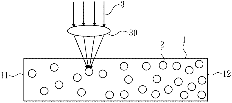
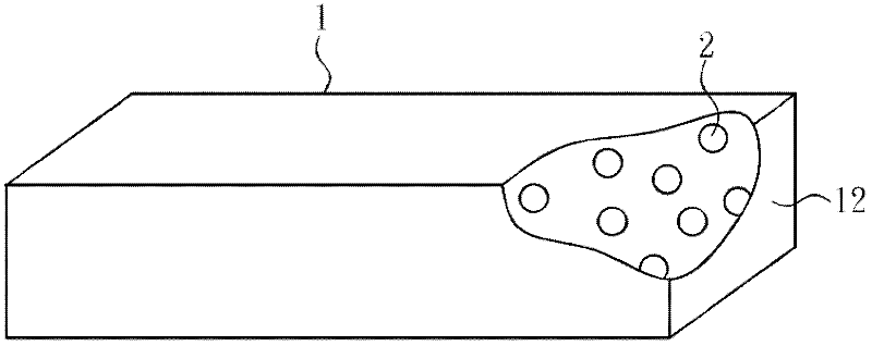
[0029] Please refer to figure 2 and image 3 as shown, figure 2 It is a side sectional view of the first embodiment of the light guide plate of the present invention, image 3 It is a perspective view of the first embodiment of the light guide plate of the present invention. The light guide plate of the present invention mainly includes a light guide plate b...


PUM


Abstract

A light guide plate and manufacturing method thereof, the light guide plate manufacturing method mainly comprising: forming a light guide plate body (1); then forming a plurality of light scattering units (2) within the light guide plate body (1), the light scattering units (2) being arranged according to a specific rule. The light scattering units (2) can reduce light guide plate color differences, avoid the generation of a dead pixel, and improve light emission efficiency.

Description

【Technical field】 [0001] The invention relates to a light guide plate, in particular to a light guide plate capable of reducing chromatic aberration and improving light emission efficiency and a manufacturing method thereof. 【Background technique】 [0002] Since the liquid crystal panel of the liquid crystal display does not have the function of self-illumination, the liquid crystal display needs to be further equipped with a backlight module to supply sufficient and evenly distributed surface light sources for the liquid crystal panel. Generally speaking, backlight modules can be mainly divided into two types: direct-type and side-type, and the light guide plate is a key component for the side-type backlight module to provide a uniform surface light source. The light guide plate uses the principle of total reflection to transmit the light entering from the side of the light guide plate to the far end of the light guide plate. [0003] In order to allow light to be evenly e...

Claims


Application Information

Patent Timeline
Patent Type & Authority Applications(China)
IPC IPC(8): G02B6/00G02B5/02
CPCG02B6/0065G02B6/0041G02B6/0061
Inventor 胡哲彰黄建发
Owner TCL CHINA STAR OPTOELECTRONICS TECH CO LTD
Why Eureka
Try Eureka