Fusion fiber optic connector

An optical fiber connector and fusion splicing technology, which is applied in the field of fusion spliced ​​optical fiber connectors, can solve the problems of limited application range and application scale, scattered connector dimensions, complicated installation process operations, etc., and achieve compact length, simplified manufacturing process requirements, The effect of simplifying on-site operations

Active Publication Date: 2011-12-28
NANJING PUTIAN TELECOMMUNICATIONS CO LTD
View PDF6 Cites 8 Cited by
  • Summary
  • Abstract
  • Description
  • Claims
  • Application Information

AI Technical Summary

Problems solved by technology

Welding solves the problems of cold splicing, improves the quality of splicing, and ensures the life of splicing. With the advent of FTTH small fusion splicing machines, field connectors made by welding appear. However, in the prior art, ceramic pins are all It adopts the method of

Method used


Image

  • Fusion fiber optic connector
  • Fusion fiber optic connector
  • Fusion fiber optic connector

Examples


Embodiment Construction

[0014] The following will clearly and completely describe the technical solutions in conjunction with the accompanying drawings in the embodiments. Apparently, the described embodiments are only some of the embodiments of the present invention, not all of them.

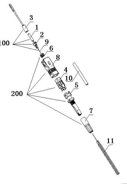
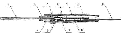
[0015] Control attached figure 1 , 2 , the fiber optic connector includes a ceramic ferrule assembly 100 and a tail assembly 200 that can be passed through on-site optical cables. The short optical fiber 9 is preset in the ceramic ferrule assembly 100, and the short optical fiber 9 passes through the tail assembly 200 that can be passed through on-site optical cables. The 11 core wires of the on-site optical cable are welded, and the fusion connection part is provided with a protective sleeve 10, and one end of the protective sleeve is connected with the ceramic pin assembly. The protective sleeve is housed in the cavity of the tail assembly and passes through the center hole of the spring. This embodiment is descri...


PUM


Abstract

The invention relates to a welding type fiber connector. The fiber connector comprises a ceramic pin assembly and a tail assembly, wherein the tail assembly can be passed through by an on-site optical fiber. A preset short optical fiber is arranged in the ceramic pin assembly and fusion is carried on the short optical fiber and a core wire of the on-site optical fiber, wherein the core wire passes through the tail assembly; a reinforced protective sleeved pipe is arranged at the fusion connection portion; and one end of the protective sleeved pipe is connected with the ceramic pin assembly. Advantages of the fiber connector are as follows: fusion is carried on a short optical fiber and a core wire of an on-site optical fiber, wherein the core wire passes through a tail assembly; it is notneeded to arrange a cold conjunction alignment precision mechanism in the connector, thereby simplifying the manufacturing technology; one end of a protective sleeved pipe is connected with a ceramicpin assembly, so that an overlapping amount between the end of the protective sleeved pipe and a cladding portion of the core wire of the fiber can be reduced; the protective sleeved pipe penetrates a centre bore of a spring, thereby shortening an occupied length of the protective sleeved pipe; a spring and an inner sleeve are installed in the tail assembly, thereby simplifying an on-site operation; and one end of the protective sleeved pipe is connected with the ceramic pin assembly and thus the protective sleeved pipe and the ceramic pin assembly can retreat synchronizedly, so that winding loss or damage of a short optical fiber can be avoided and thus the quality of the connector is reliable.

Description

technical field [0001] The invention relates to a fusion-splicing optical fiber connector, which belongs to the technical field of optical fiber connection. Background technique [0002] With the continuous development of optical fiber communication technology, optical fiber wiring is widely used. In the case of local optical fiber wiring, etc., it is necessary to install optical fiber connectors on the optical fiber cables on site. At present, the field connectors made by cold connection have extremely high requirements on the manufacturing process, so that there are great problems in the quality, efficiency, pass rate and life of cold connection when they are applied in batches, especially the connection success rate and performance. Compared with welding, there are still great shortcomings. Welding solves the problems of cold splicing, improves the quality of splicing, and ensures the life of splicing. With the advent of FTTH small fusion splicing machines, field connect...

Claims


Application Information

Patent Timeline
IPC IPC(8): G02B6/38G02B6/255
Inventor 曾大庆张登平朱钰
Owner NANJING PUTIAN TELECOMMUNICATIONS CO LTD
Why Eureka
Try Eureka