A Direct Voltage Sine Wave Driving Method for Brushless DC Motor

A technology of brushless DC motor and driving method, applied in the direction of electronic commutator, torque ripple control, etc., can solve the problems of few practical projects, and achieve the effect of large starting torque, low noise and constant torque

Inactive Publication Date: 2011-12-28
中国航天科技集团公司第四研究院四〇一所
View PDF3 Cites 8 Cited by
  • Summary
  • Abstract
  • Description
  • Claims
  • Application Information

AI Technical Summary

Problems solved by technology

[0005] At present, there have been research and practical cases of sine wave drive in foreign literature; while there are

Method used


Image

  • A Direct Voltage Sine Wave Driving Method for Brushless DC Motor
  • A Direct Voltage Sine Wave Driving Method for Brushless DC Motor
  • A Direct Voltage Sine Wave Driving Method for Brushless DC Motor

Examples


Embodiment Construction

[0037] Now in conjunction with embodiment, accompanying drawing, the present invention will be further described:

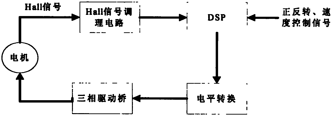
[0038] The brushless DC motor controller mainly determines the position of the motor rotor by collecting the signal of the position sensor in the motor, and realizes the commutation of the motor by controlling the on-off of the electronic commutator through the position of the motor rotor. The block diagram of the DC brushless motor control principle is as follows: figure 1 shown.

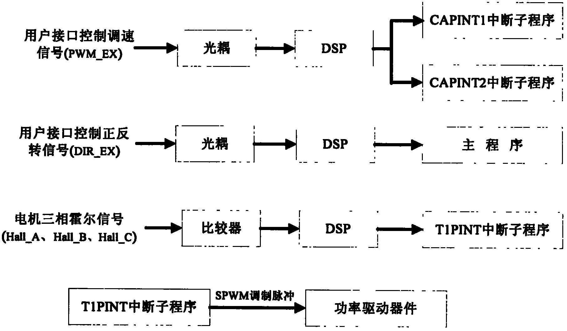
[0039] From figure 2 It can be known that the external input signal of the sine wave driver (that is, the motor three-phase Hall signal Hall_A, Hall_B, Hall_C) and the external control signal (that is, the user interface control speed signal PWM_EX, the forward and reverse signal DIR_EX) and the sine wave driver microprocessor hardware And the interface relationship between each subroutine software, so as to clarify the signals of the sine wave driver and the system software and ha...


PUM


Abstract

The invention proposes a direct voltage sine wave driving method for a DC brushless motor, and the sine wave driver can completely replace the square wave driver. The sine wave drive DC brushless motor system has the characteristics of constant torque, low noise, large starting torque, excellent low-speed performance, good dynamic performance and adjustable torque. Compared with the traditional square wave drive, it has great advantages, especially in terms of precision requirements. Higher servo control system. Especially in low-speed operating systems, sine wave drives have incomparable advantages.

Description

technical field [0001] The invention relates to a direct voltage sine wave driving method of a DC brushless motor, belongs to the technical field of motor control, and relates to the sine wave control of a DC brushless motor. More specifically, it relates to a method for realizing the driving of the DC brushless motor with the advantages of large starting torque, high efficiency, excellent low-speed performance, good dynamic performance, low noise, and adjustable torque. Background technique [0002] The brushless motor consists of three parts: the motor body, the position sensor, and the drive control circuit. In the motor system, due to the existence of cogging torque, the output torque fluctuates, causing vibration and noise, and affecting the control accuracy of the system. With the further development of technical requirements, especially the precision servo system requires further improvement and promotion in the development of motors and motor drives. [0003] In th...

Claims


Application Information

Patent Timeline
IPC IPC(8): H02P6/10H02P6/16
Inventor 郗珂庆张琴琴方卫冯楠
Owner 中国航天科技集团公司第四研究院四〇一所
Why Eureka
Try Eureka