Power supply with two series inverters for a polyphase electromechanical actuator

a technology of electromechanical actuator and power supply, which is applied in the direction of electronic commutators, motor/generator/converter stoppers, dynamo-electric converter control, etc., can solve the problems of not being able to continue to operate the rotary machine correctly, being subjected to torque with a high degree of ripple, and being harmful in certain applications. , to achieve the effect of constant torque, constant torque and constant torqu

Active Publication Date: 2010-06-10
SAFRAN LANDING SYSTEMS
View PDF5 Cites 9 Cited by
  • Summary
  • Abstract
  • Description
  • Claims
  • Application Information

AI Technical Summary

Benefits of technology

[0009]If one of the windings becomes disconnected from one of the arms, such that the corresponding phase can no longer be controlled, it is possible to power the good phases with currents presenting a sum that is not constantly zero so as to enable the motor to turn with constant torque. The residual current coming from the non-zero sum of the currents in the good phases is drained via the bridge so as to be returned to the inverter that is generating such currents. The presence of the bridge and of the additional arms thus enables the actuator to be operated at constant torque.
[0010]In particular, with a three-phase motor having one of its phases disconnected, it is possible by suitably controlling the switches to create a common point between the two good phases and the bridge, thereby enabling the actuator to operate at constant torque in a two-phase mode: by providing power supply currents that are phase-shifted by π / 3, while the phases are themselves spatially phase offset by an angle equal to 2π / 3, constant torque is obtained. This enables operation to continue at constant torque, even in the event of one of the phases being disconnected.

Problems solved by technology

Nevertheless, such an architecture does not make it possible to continue operating the rotary machine correctly if the end of one of the windings becomes disconnected from the corresponding arm.
If the switches of the inverters continue to be controlled as though one of the windings had not become disconnected, then the machine would be subjected to torque with a high degree of ripple, which can be very harmful in certain applications, for example actuating high-lift devices of an aircraft, or actuating landing gear.

Method used


Image

  • Power supply with two series inverters for a polyphase electromechanical actuator
  • Power supply with two series inverters for a polyphase electromechanical actuator
  • Power supply with two series inverters for a polyphase electromechanical actuator

Examples


Embodiment Construction

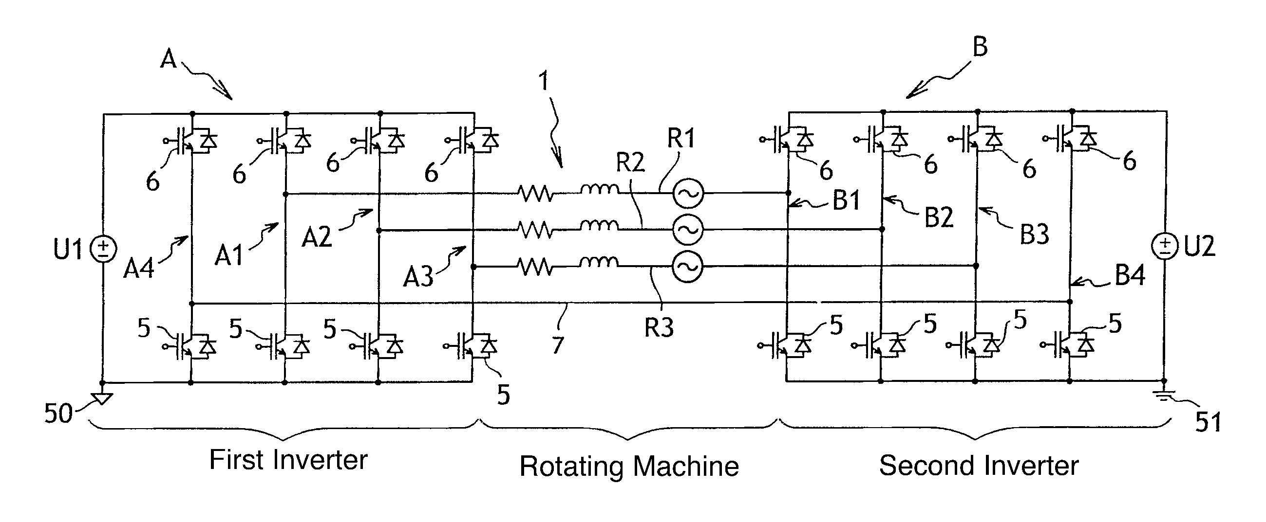
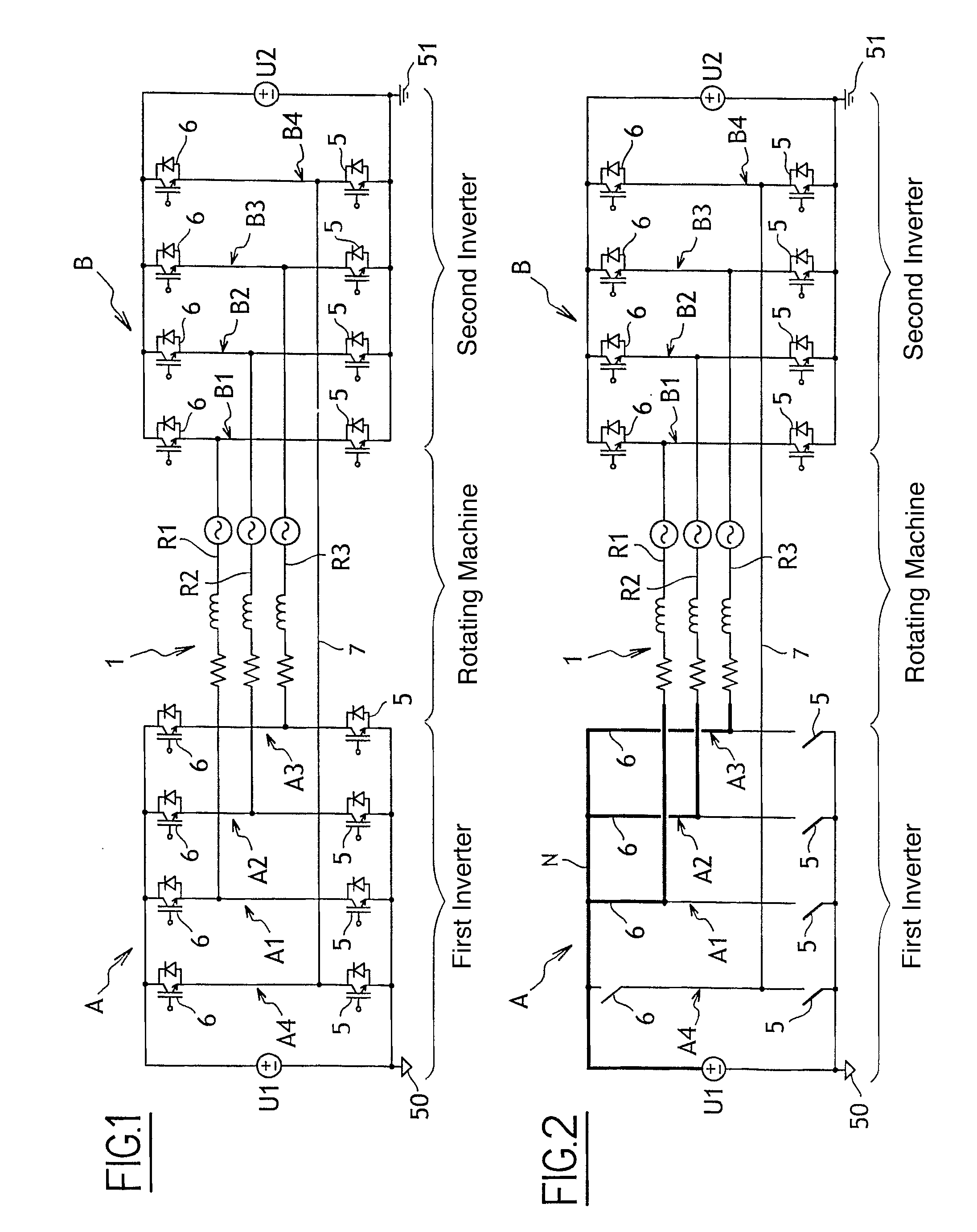
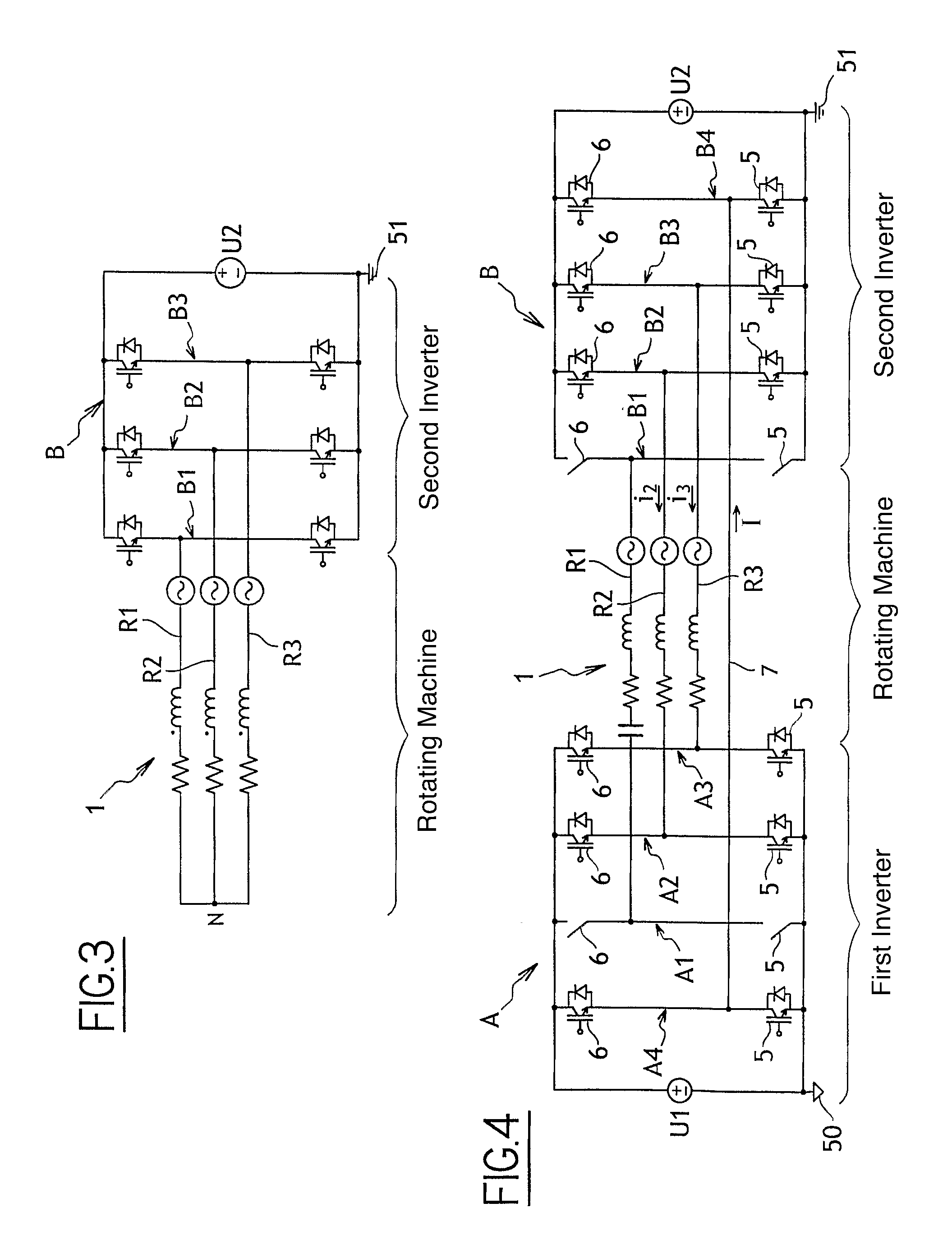
[0018]With reference to FIG. 1, the power supply architecture is shown here in application to an electromechanical actuator provided with a three-phase electric motor or rotary machine 1, represented by three windings R1, R2, and R3, each symbolized conventionally as a resistor, an inductor, and a back electromotive force (back e.m.f.) connected in series. Each of the windings forms one of the phases of the rotary machine, and each is offset spatially by 2π / 3 relative to other windings. The power supply of the invention shown here comprises a first converter or inverter A and a second converter or inverter B.

[0019]The inverter A comprises a first voltage source U1 having one of its terminals connected to a first ground 50. Across the terminals of the first voltage source U1, there extend three arms A1, A2, and A3, each comprising an upstream controlled switch 5 and a downstream controlled switch 6 that are connected in series along the arm. By way of example, the controlled switches...


PUM


Abstract

The invention relates to a power supply having two inverters (A, B) in series for powering an electromechanical actuator having an electric motor including a plurality of windings (R1, R2, R3) forming phases, each inverter being connected to its own ground (50; 51) and having a voltage source (U1; U2) having as many arms (A1, A2, A3; B1, B2, B3) as there are windings to be powered, each arm including two controlled switches (5, 6) connected in series, with a point therebetween being provided for connection to one end of one of the windings. According to the invention, each inverter includes an additional arm (A4; B4) having two controlled switches, the two additional arms being interconnected by a bridge (7) that is connected to each of the additional arms at a point that is situated between the switches.

Description

[0001]The invention relates to a power supply having two inverters in series for a polyphase electromechanical actuator.BACKGROUND OF THE INVENTION[0002]In order to power an electromechanical actuator having a polyphase motor including windings that form phases, it is known to use power supplies comprising two inverters connected in series. Each inverter has a voltage source with its terminals connected to as many arms as there are windings for powering on the machine. Each arm comprises an upstream controlled switch and a downstream controlled switch connected in series. Each winding has a first end connected to one of the arms of one of the inverters, at a point that is situated between the controlled switches of said arm, and a second end connected to one of the arms of the other inverter, likewise at a point situated between the controlled switches of said arm.[0003]If one of the controlled switches in one of the arms of one of the inverters fails, so as to remain permanently op...

Claims


Application Information

Patent Timeline
Patent Type & Authority Applications(United States)
IPC IPC(8): H02P6/00
CPCH02M7/5387H02P29/022H02P27/06H02P29/032
Inventor MATT, DANIELJAC, JULIENZIEGLER, NICOLAS
Owner SAFRAN LANDING SYSTEMS
Why Eureka
Try Eureka