
Multi-link transparent interconnection multicast frame transmission method and system

A technology of multi-link transparency and transmission method, which is applied in the field of multi-link transparent interconnection and multicast frame transmission, which can solve problems such as waste of investment, exhaustion of MAC address space of edge devices, and loss of Layer 2 network, etc., to ensure smooth expansion , bandwidth prevention, and the effect of reducing report loss

Active Publication Date: 2011-12-28
武汉神州数码云科网络技术有限公司
View PDF5 Cites 34 Cited by
  • Summary
  • Abstract
  • Description
  • Claims
  • Application Information

AI Technical Summary

Problems solved by technology

[0003] In the future, the horizontal traffic inside the data center will become larger and larger, and STP still needs to be run between the newly added device and the original device. If only one link between the two servers is feasible, the rest of the 10 Gigabit switch ports will be blocked. Not only is it a great waste of investment, but it also cannot support the rapid expansion of services; secondly, when the number of cross-links increases, the design of the Layer 2 network will become very complicated, which link should be reserved and which link should be blocked , and also consider where the layer-3 gateway is located, which loses the advantages of simple layer-2 network configuration; finally, the traditional layer-2 MAC address has no hierarchical concept, which can easily lead to the exhaustion of the MAC address space of edge devices , especially in a virtualized data center, the number of MAC addresses of virtual machines may be thousands

Method used

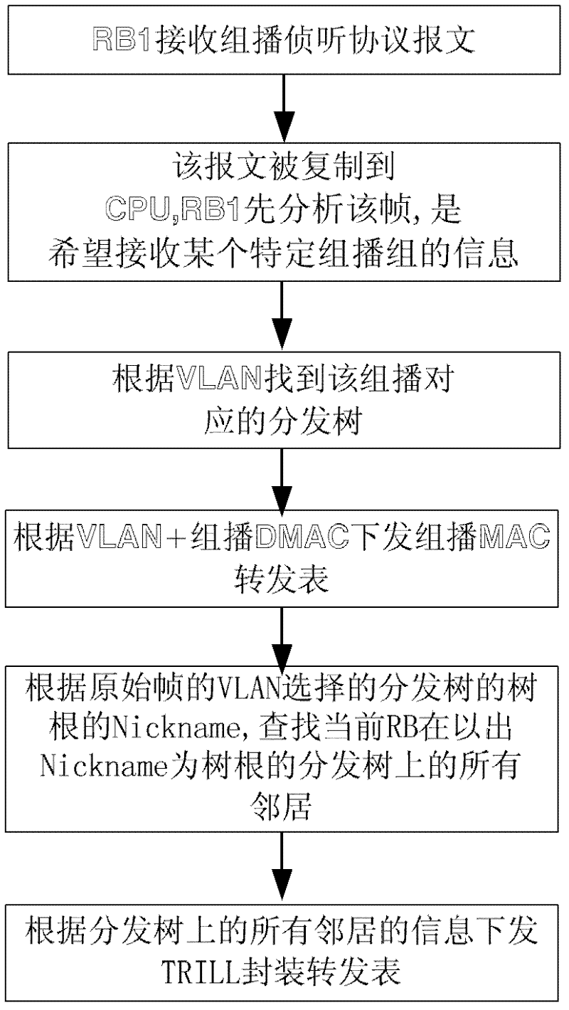
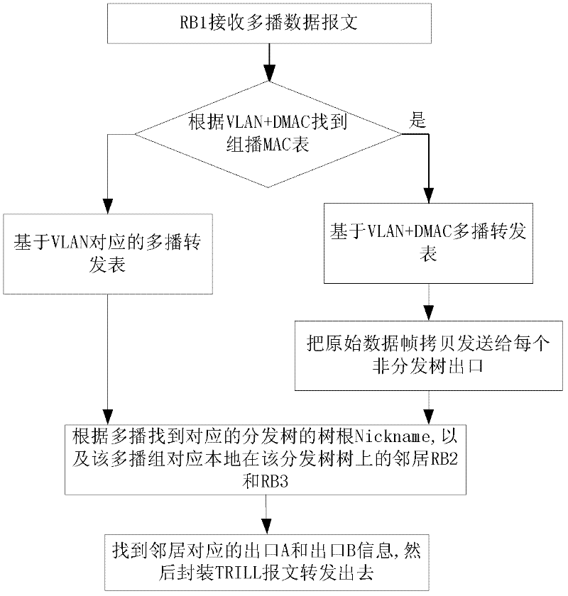

Image

  • Multi-link transparent interconnection multicast frame transmission method and system
  • Multi-link transparent interconnection multicast frame transmission method and system
  • Multi-link transparent interconnection multicast frame transmission method and system

Examples


Embodiment Construction

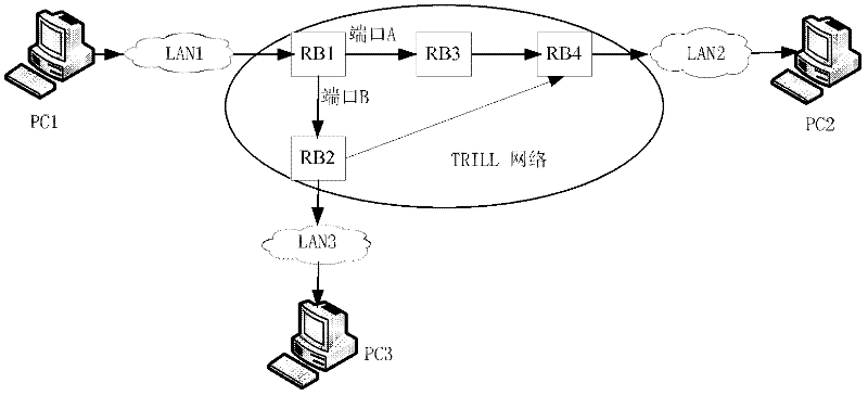
[0030] Such as figure 1 As shown, a schematic diagram of the TRILL network connection structure of four sub-switches is given: each switch uses RB instead, figure 1 PC1, PC2 and PC3 are client devices, PC1 is connected to LAN1, PC2 is connected to LAN2, PC3 is connected to LAN3, edge switch RB1 is TRILL network edge device, intermediate switch RB3 is TRILL network transmission device; the port of RB1 A is connected to the switch RB3, and port B is connected to the edge switch RB2; RB2 and RB3 are connected to the TRILL network edge device RB4, where RB2 can be used as an edge device or as a transmission device.

[0031] Port A and port B on the edge switch RB1 are two paths in the TRILL network. The links connected from port A and port B not only transmit the traffic generated by RB1, but also back up each other at the same time.

[0032] Each RB recognizes the topology of the TRILL network by running its own link state protocol, generates a distribution tree, and generates a...


PUM


Abstract

The invention discloses a multi-link transparent interconnection multicast frame transmission method and system, which recognizes the topology of the TRILL network through the link state protocol and generates a distribution tree; according to the received multicast listening protocol message and the route of the RB The forwarding table information generates a multicast TRILL forwarding table; when the RB receives a VLAN broadcast frame or multicast frame, the RB encapsulates the data frame as a TRILL data frame and sends it to the TRILL network; when a fault is detected, the channel status is changed to allow the TRILL data Packet smooth switching and forwarding. Adopting the technical solution of the present invention effectively guarantees the transmission of multicast messages in the TRILL network, fully utilizes the bandwidth and effectively prevents broadcast storms, well supports the rapidly increasing horizontal traffic between servers, and ensures the smooth expansion of the two-layer network , effective hierarchical MAC address, providing guarantee for virtualized data center business expansion.

Description

technical field [0001] The invention relates to the technical field of data transmission in a data center network, in particular to a multi-link transparent interconnection multicast frame transmission method and system. Background technique [0002] Most of today's data center networks are built following the standard hierarchical concept, which is divided into access layer and aggregation / core layer. All Layer 2 links run the Spanning Tree Protocol (STP). When more than one path is reachable between any two points, STP will block the redundant path to ensure that there is only one path between the two points. up to prevent loops. This mode has been adopted on a large scale for a long time in the past, because it is very simple to deploy, access layer devices do not require complex configuration, and most network policies can be distributed to the entire network as long as they are deployed centrally at the aggregation layer. But as the size of the data center continues t...

Claims


Application Information

Patent Timeline
Patent Type & Authority Applications(China)
IPC IPC(8): H04L12/56H04L12/24H04L45/28H04L45/16
Inventor 陈振光
Owner 武汉神州数码云科网络技术有限公司
Learn More