A led dimming system

A dimming and constant current module technology, applied in the field of LED dimming systems, can solve problems such as poor power factor, reduced efficiency of LED driver 12, large electromagnetic interference, etc., and achieves low electromagnetic interference, high reliability, and strong anti-interference ability Effect

Active Publication Date: 2011-12-28
INVENTRONICS HANGZHOU
View PDF4 Cites 11 Cited by
  • Summary
  • Abstract
  • Description
  • Claims
  • Application Information

AI Technical Summary

Problems solved by technology

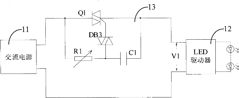
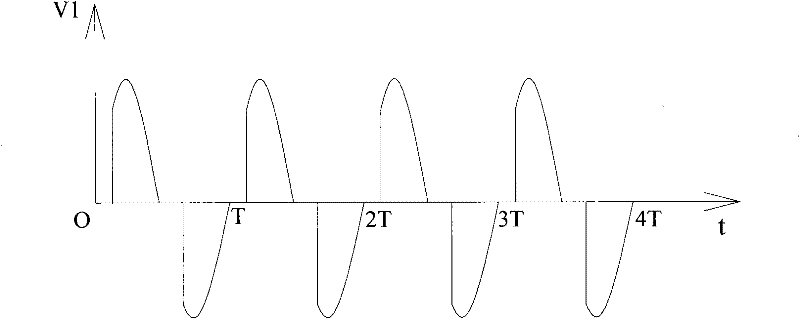
[0007] This method controls the output current of the LED driver 12 by changing the chopping angle of the voltage V1, which is an ideal low-cost dimming solution, but the inherent disadvantages of chopping dimming are poor power factor and large electromagnetic interference in the dimming state. , when applied to switching power supply LED drivers, there is an impedance matching problem between the dimmer 13 and the switching power supply 11 load, and solving the matching problem will often lead to a significant reduction in the efficiency of the LED driver 12

Method used


Image

  • A led dimming system
  • A led dimming system
  • A led dimming system

Examples


Embodiment Construction

[0034] In order to make the above objects, features and advantages of the present invention more comprehensible, the present invention will be further described in detail below in conjunction with the accompanying drawings and specific embodiments.

[0035] see Figure 4 , shows the first embodiment of the LED dimming system of the present invention, including a voltage regulator converter 21, the two input terminals of the voltage regulator converter 21 are connected to the power supply, and the positive output terminals are respectively connected to the positive input terminals of the constant current module 22 for voltage stabilization conversion The negative output terminal of the device 21 is connected to the negative input terminal of the constant current module through the switching tube S1 controlled by the PWM signal, and multiple LED loads connected in series are connected between the positive and negative output terminals of the constant current module.

[0036] The...


PUM


Abstract

The invention relates to a light emitting diode (LED) dimming system comprising a voltage stabilizing transformer and a constant current module, wherein, the input end of the voltage stabilizing transformer is connected with a power source; the output end of the constant current module is connected with at least one tandem LED load; the output end of the voltage stabilizing transformer is connected with the input end of the constant current module through a switching tube; and the on and off of the switching tube are controlled by a PWM (pulse-width modulation) signal. The LED dimming system provided by the invention has the advantages of high power factor and little electromagnetic interference and being easy to realize and the like.

Description

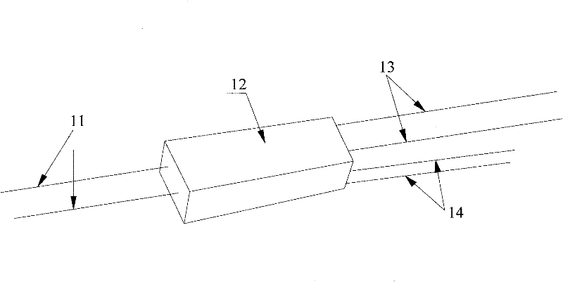
technical field [0001] The invention relates to the field of electronic circuits, in particular to a centralized control LED dimming system. Background technique [0002] LED lighting has outstanding advantages such as energy saving and high light efficiency, and is widely used in various lighting places. During use, the brightness of the LED load needs to be adjusted according to different requirements [0003] figure 1 A commonly used scheme for dimming LEDs through an external dimmer is shown. Wherein, the LED driver 12 is provided with an input line 11 and an output line 13, wherein the LED driver 12 is connected to a power supply through the input line 11, and the output line 13 is connected to the LED, and outputs a driving current for the LED. In addition, the dimming signal line from the external dimmer is also connected to the LED driver 12, and the user can adjust the dimming signal input to the LED driver 12 through the external dimmer, so that the LED driver 1...

Claims


Application Information

Patent Timeline
Patent Type & Authority Applications(China)
IPC IPC(8): H05B37/02
CPCH05B33/0827H05B45/3725H05B45/375H05B45/38H05B45/385H05B45/395H05B45/46Y02B20/30
Inventor 葛良安华桂潮
Owner INVENTRONICS HANGZHOU
Why Eureka
Try Eureka