Disk Mounting Device

A technology for specifying positions and frames, applied in the directions of record carrier structural parts, filamentary/network record carriers, input/output to record carriers, etc. Height, size, etc.

Inactive Publication Date: 2011-12-28
FUJITSU LTD
View PDF2 Cites 4 Cited by
  • Summary
  • Abstract
  • Description
  • Claims
  • Application Information

AI Technical Summary

Problems solved by technology

Therefore, it cannot be mounted on a disk mounting device in a state where two types of HDDs, 3.5-inch and 2.5-inch, are mixed.
[0008] Here, although a 2.5-inch HDD can be mounted in the socket of a 3.5-inch disk mounting device, in this case, there is a problem that the small size advantage of the 2.5-inch type is impaired.
[0009] In addition, there is a problem that when two 2.5-inch type HDDs are mounted in the depth direction of the socket portion formed as a 3.5-inch type of the disk mounting device, the HDD mounted on the rear side must be pulled out every time. Take it out behind the HDD on the front side
However, in this case, since it is necessary to secure a space for passing the HDD 40 on the rear side, there is a problem that the height and size of the disk mounting device 10 become large (height H

Method used


Image

  • Disk Mounting Device
  • Disk Mounting Device
  • Disk Mounting Device

Examples


Embodiment 1

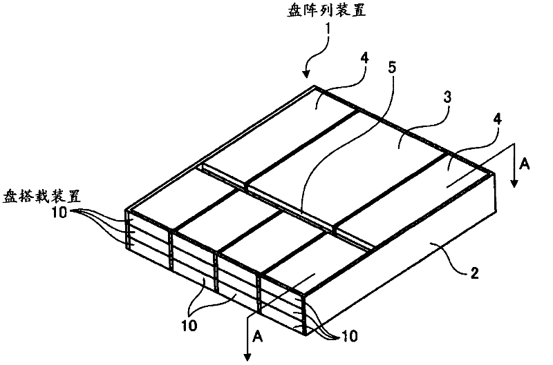
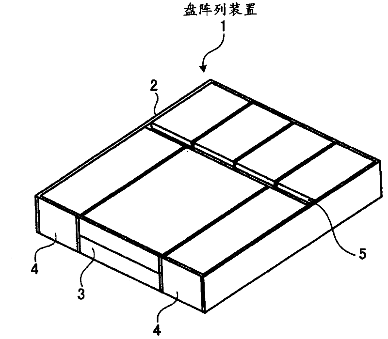
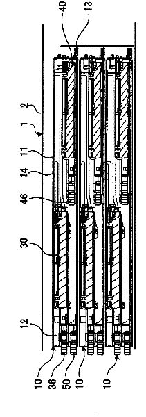
[0036] figure 1 It is a perspective view showing the appearance of the front side of the disk array device of the first embodiment. in addition, figure 2 yes means figure 1 A perspective view of the inside appearance of the disk array device. in addition, image 3 yes means figure 1 A-A sectional view of the interior of the disk array device. in addition, Figure 4 is to indicate that the image 3 A diagram showing the operation of the disk mounting device inside the disk array device.

[0037] [Structure of Disk Array Device]

[0038] Such as Figure 1 ~ Figure 4 As shown, the disk array device 1 is formed in a square shape as a whole, and has a plurality of (inside figure 1 Among them are 12 disk mounting devices 10 in 4 rows and 3 layers, and a control board 3 for controlling the above-mentioned plurality of disk mounting devices 10 . In addition, the disk mounting device 10 is electrically connected to the power supply unit 4 that supplies electric power to...


PUM


Abstract

The disk mounting device (10) holds two HDDs (30), (40) inside the external housing (11) forming the disk mounting device (10), and an internal housing (20) is arranged, and the internal housing ( 20) There are guide grooves (23), (24) respectively formed with oblique grooves (25) and parallel grooves (26), and when pulling out the inner box (20), make the HDD (30) on the front side Raise it vertically to a position where the HDD (40) on the inside is not hindered from being pulled out.

Description

technical field [0001] The present invention relates to a disk mounting device. Background technique [0002] Conventionally, magnetic disk devices have been widely used as external storage devices capable of large-capacity and high-speed data transfer. In particular, in recent years, a disk array device including a plurality of disk mounting devices has been used as an external storage device realizing high reliability and low cost (Patent Documents 1 to 2). [0003] The disk mounting device is a device that accommodates a plurality of small magnetic disk devices (hereinafter, simply referred to as "HDD"), and distributes and stores data to each HDD. This disk mounting device uses two types of HDDs: a 3.5-inch HDD for low-cost / high-capacity (first specification) and a 2.5-inch HDD for small / high-speed (second specification). [0004] Patent Document 1: Japanese Patent Laid-Open No. 2006-235964 [0005] Patent Document 2: Japanese Patent Laid-Open No. 2003-36669 [0006]...

Claims


Application Information

Patent Timeline
Patent Type & Authority Applications(China)
IPC IPC(8): G11B33/12G06F3/06
CPCG11B33/128G11B15/6885G06F3/06G11B33/12
Inventor 山田悟
Owner FUJITSU LTD
Why Eureka
Try Eureka