Four-channel optical fiber standard frequency module that can realize soft and hard cross switching based on Ethernet bus
What is Al technical title?
Al technical title is built by PatSnap Al team. It summarizes the technical point description of the patent document.
An Ethernet, four-channel technology, applied in the direction of optical fiber transmission, bus network, data exchange through path configuration, etc., can solve the problems of large number, many modules, occupying a lot of space, etc., to achieve high transmission rate, smooth upgrade, communication good reliability
Active Publication Date: 2016-08-10
PANDA ELECTRONICS GROUP +1
View PDF5 Cites 0 Cited by
Summary
Abstract
Description
Claims
Application Information
AI Technical Summary
This helps you quickly interpret patents by identifying the three key elements:
Problems solved by technology
Method used
Benefits of technology
Problems solved by technology
[0002] The existing standard frequency modules generally only provide one radio frequency signal. To provide four standard frequency signals, four standard frequency modules are required. There are many modules and occupy a lot of space.
At the same time, because the multi-band communication system needs to convert the digital intermediate frequency electrical signal into an optical signal and send it to the remote transmitter, the previous photoelectric conversion module only has the photoelectric conversion function of one channel, so four such photoelectric conversion modules are needed, and there are also a relatively large number of photoelectric conversion modules. many questions
Method used
Image
Click on the blue label to locate the original text in one second.
Reading with bidirectional positioning of images and text.
Examples
Embodiment Construction
[0010] In order to better understand the technical content of the present invention, specific embodiments are given together with the attached drawings for description as follows.
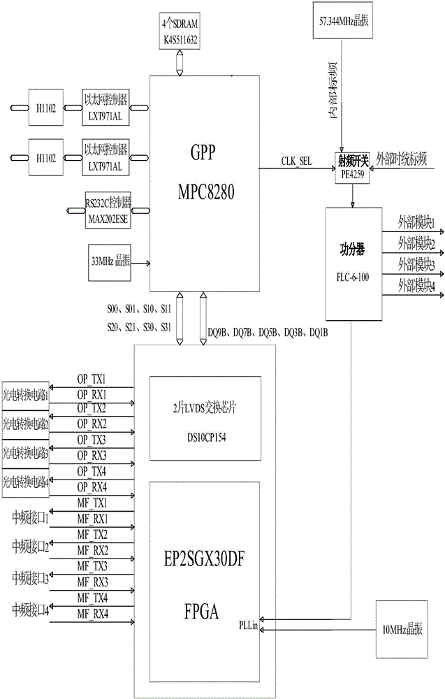
[0011] like figure 1 As shown, the four-channel optical fiber standard frequency module communicates with the main control system through the Ethernet bus, and the digital signals of the external 4-channel intermediate frequency module are transmitted to the four-channel optical fiber standard frequency module through the LVDS level, and are converted internally through 4-channel photoelectric conversion. into an optical signal. The optical fiber standard frequency module is connected to the 4-way radio frequency module of the remote transmitter through optical fiber to transmit optical signals.
[0012] figure 2 It is a specific schematic diagram of the four-channel optical fiber standard frequency module of the embodiment of the present invention. The four-channel optical fiber standard frequ...
PUM
Abstract
The invention provides an Ethernet bus-based four-channel optical fiber standard frequency module capable of realizing alternative soft and hard switching. The four-channel optical fiber standard frequency module comprises a power supply module, a power divider, four photoelectric conversion circuits, one PPC chip, one FPGA chip, four SRAM chips, two FLASH chips, two Ethernet interface chips, one RS232 interface chip, a radio frequency switch chip and two LVDS exchange chips, wherein the power supply module supplies power for the power divider, the photoelectric conversion circuits, the PPC chip, the FPGA chip, the SRAM chips, the FLASH chips, the Ethernet interface chips, the RS232 interface chip, the radio frequency switch chip and the LVDS exchange chips; and the FPGA chip, the SRAM chips, the FLASH chips, the Ethernet interface chips, the RS232 interface chip, the radio frequency switch chip and the LVDS exchange chips are connected with the PPC chip respectively. The four-channel optical fiber standard frequency module of the invention can realize the soft and hard switching of LVDS through using the FPGA chip or the PPC chip; and an Ethernet bus is adopted between the four-channel optical fiber standard frequency module and a main control module. The four-channel optical fiber standard frequency module is advantageous in high transmission speed, high reliability in communication and the like.
Description
technical field [0001] The invention belongs to the field of electronic circuit design, and in particular relates to a four-channel optical fiber standard frequency module that can realize soft and hard cross switching based on the Ethernet bus. Background technique [0002] Existing standard frequency modules generally only provide one radio frequency signal. To provide four standard frequency signals, four standard frequency modules are required. There are many modules and occupy a lot of space. At the same time, because the multi-band communication system needs to convert the digital intermediate frequency electrical signal into an optical signal and send it to the remote transmitter, the previous photoelectric conversion module only has the photoelectric conversion function of one channel, so four such photoelectric conversion modules are needed, and there are also a relatively large number of photoelectric conversion modules. many questions. Contents of the invention ...
Claims
Application Information
Patent Timeline
Application Date:The date an application was filed.
Publication Date:The date a patent or application was officially published.
First Publication Date:The earliest publication date of a patent with the same application number.
Issue Date:Publication date of the patent grant document.
PCT Entry Date:The Entry date of PCT National Phase.
Estimated Expiry Date:The statutory expiry date of a patent right according to the Patent Law, and it is the longest term of protection that the patent right can achieve without the termination of the patent right due to other reasons(Term extension factor has been taken into account ).
Invalid Date:Actual expiry date is based on effective date or publication date of legal transaction data of invalid patent.