
Electronic door control lock

An electronic lock and access control technology, which is applied in the field of electronic locks, can solve problems such as being easily opened by violence, battery exhaustion, and increased volume and weight of electronic locks.

Inactive Publication Date: 2012-01-04
吴斐
View PDF6 Cites 15 Cited by
  • Summary
  • Abstract
  • Description
  • Claims
  • Application Information

AI Technical Summary

Problems solved by technology

[0002] Existing access control is often composed of an access control device and an access control lock. The access control device must be installed on a dedicated power box on the wall and connected to an external power supply, while the access control lock is usually installed on the top of the glass door with a structure similar to a bolt. And it is wired with the access control device; the installation position of the access control device of the existing access control device is restricted by the position of the wall power box, and the bolt-type structure of the access control lock is easily opened by violence, which has poor reliability and poor security.
[0003] Existing electronic locks are usually unlocked by magnetic card identification, which has a battery box and a magnetic card identification circuit inside. If fingerprints and passwords are required to unlock the lock, a corresponding identification module must be installed in the lock body. In this way, the volume and weight of the electronic lock must be In addition, electronic locks with battery boxes will also encounter the problem of battery depletion

Method used


Image

  • Electronic door control lock
  • Electronic door control lock
  • Electronic door control lock

Examples


Embodiment Construction

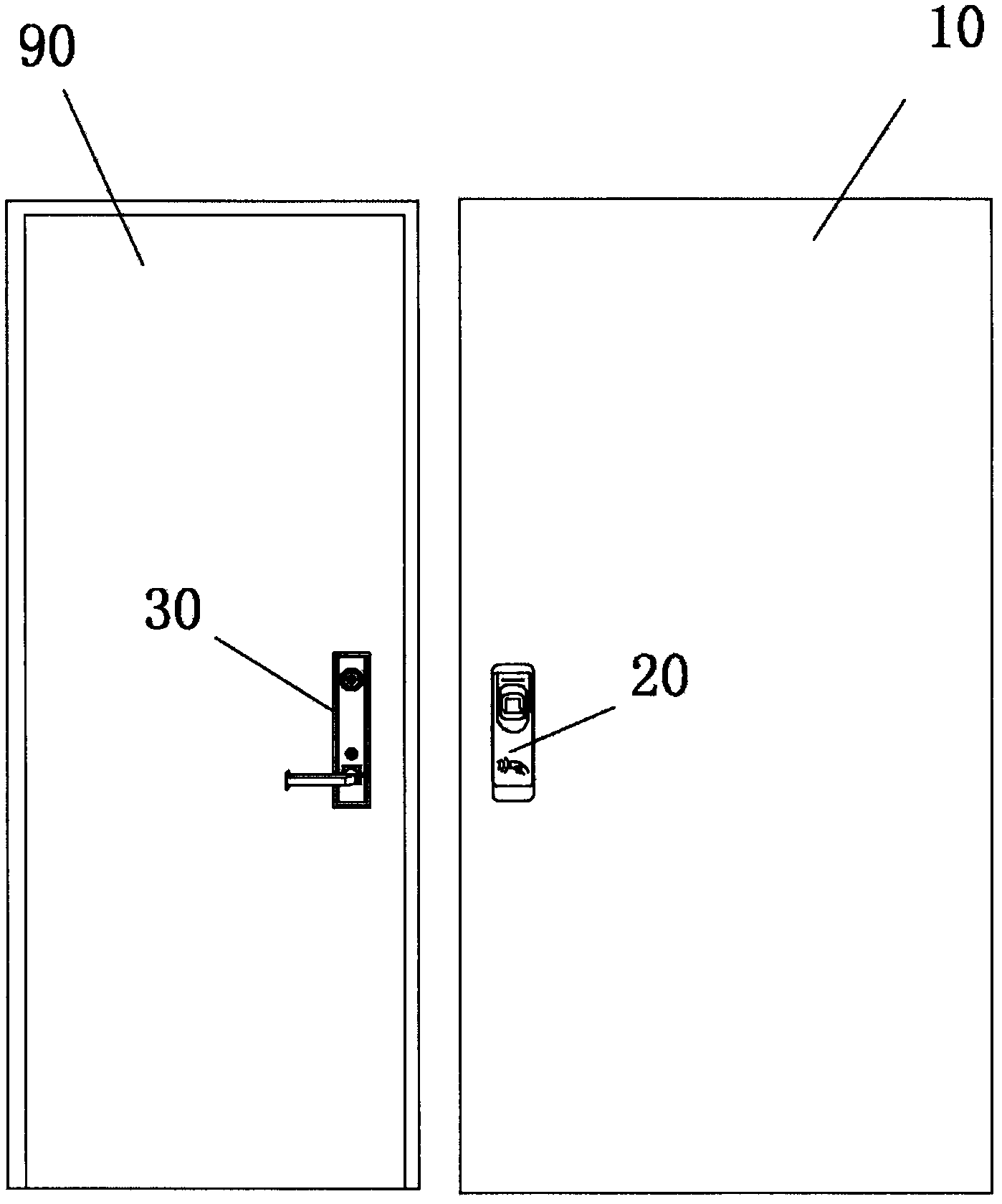
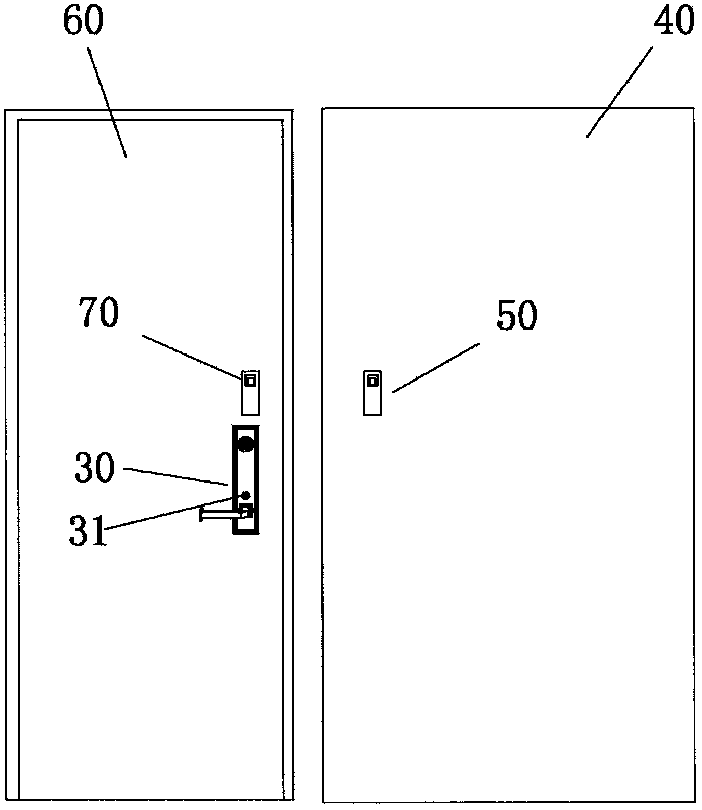
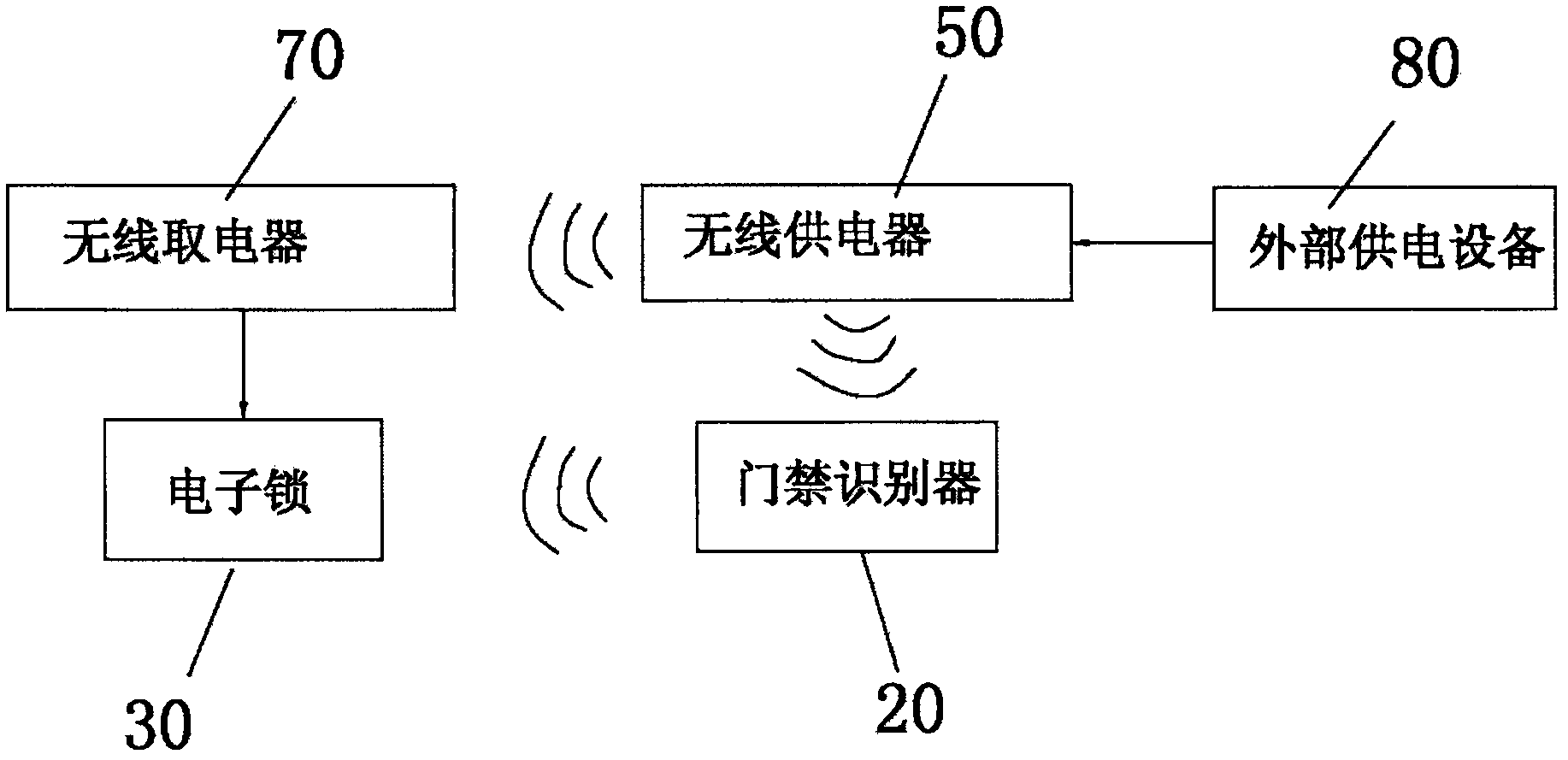
[0016] Such as Figure 1-3 As shown, the present invention includes: an access control electronic lock, including: an access control identifier 20 installed on the outer wall 10 and an electronic lock 30 installed on the door; The wireless power supply 50 at position 40 and the wireless power taker 70 installed next to the electronic lock 30 of the inner door panel 60;

[0017] The electronic lock 30 is composed of a control circuit without an internal power supply, a mechanical lock cylinder, and a motor that controls the opening and closing of the mechanical lock cylinder; the wireless power supply 50 is connected to an external power supply device 80 and has a power supply electromagnetic coil that forms an alternating magnetic field in the wireless power supply 50 , the wireless electrical take-off 70 is equipped with a power-fetching induction closed coil that receives the wireless induction alternating magnetic field and converts it into an induced current and a recharge...


PUM


Abstract

The invention relates to the technical field of electronic locks, and in particular relates to an electronic door control lock which has small and smart structure and high security, and is wirelessly powered and conveniently used. The electronic door control lock comprises a door control identifier arranged on an outer wall and an electronic lock arranged on a door as well as a wireless power supply arranged at a position corresponding to the inner wall of the door control identifier and a wireless power-using device arranged beside the electronic lock on an inner door panel. By adopting the structure, power is respectively supplied to the door control identifier and the wireless power-using device by the wireless power supply in a wireless manner; on one hand, the restriction that the traditional door control is required to be arranged on a power supply box on a wall is overcome, on the other hand, the wireless power-using device and the electronic lock are designed in a split mode, and batteries are not required to be arranged in the electronic lock, thus volume of the electronic lock is greatly reduced.

Description

technical field [0001] The invention relates to the technical field of electronic locks, in particular to an access control electronic lock with compact structure, wireless power supply, convenient use and high safety. Background technique [0002] Existing access control is often composed of an access control device and an access control lock. The access control device must be installed on a dedicated power box on the wall and connected to an external power supply, while the access control lock is usually installed on the top of the glass door with a structure similar to a bolt. And it is wired with the access control device; the installation position of the access control device of the existing access control device is restricted by the position of the wall power box, and the bolt-type structure of the access control lock is easily opened by violence, which has poor reliability and poor security. . [0003] Existing electronic locks are usually unlocked by magnetic card i...

Claims


Application Information

Patent Timeline
IPC IPC(8): G07C9/00G06K7/00G06K9/00E05B47/00E05B49/00
Inventor 吴斐
Owner 吴斐
Learn More