Communication system

A communication system and signal technology, applied in the field of communication systems, can solve problems such as difficulties and different receiving characteristics

Inactive Publication Date: 2014-05-07
FUJITSU LTD
View PDF6 Cites 0 Cited by
  • Summary
  • Abstract
  • Description
  • Claims
  • Application Information

AI Technical Summary

Problems solved by technology

However, the reception characteristics of each user are different due to the state of each transmission path, so it is very difficult to directly determine the optimal spreading rate for each user

Method used


Image

  • Communication system
  • Communication system
  • Communication system

Examples


no. 1 approach

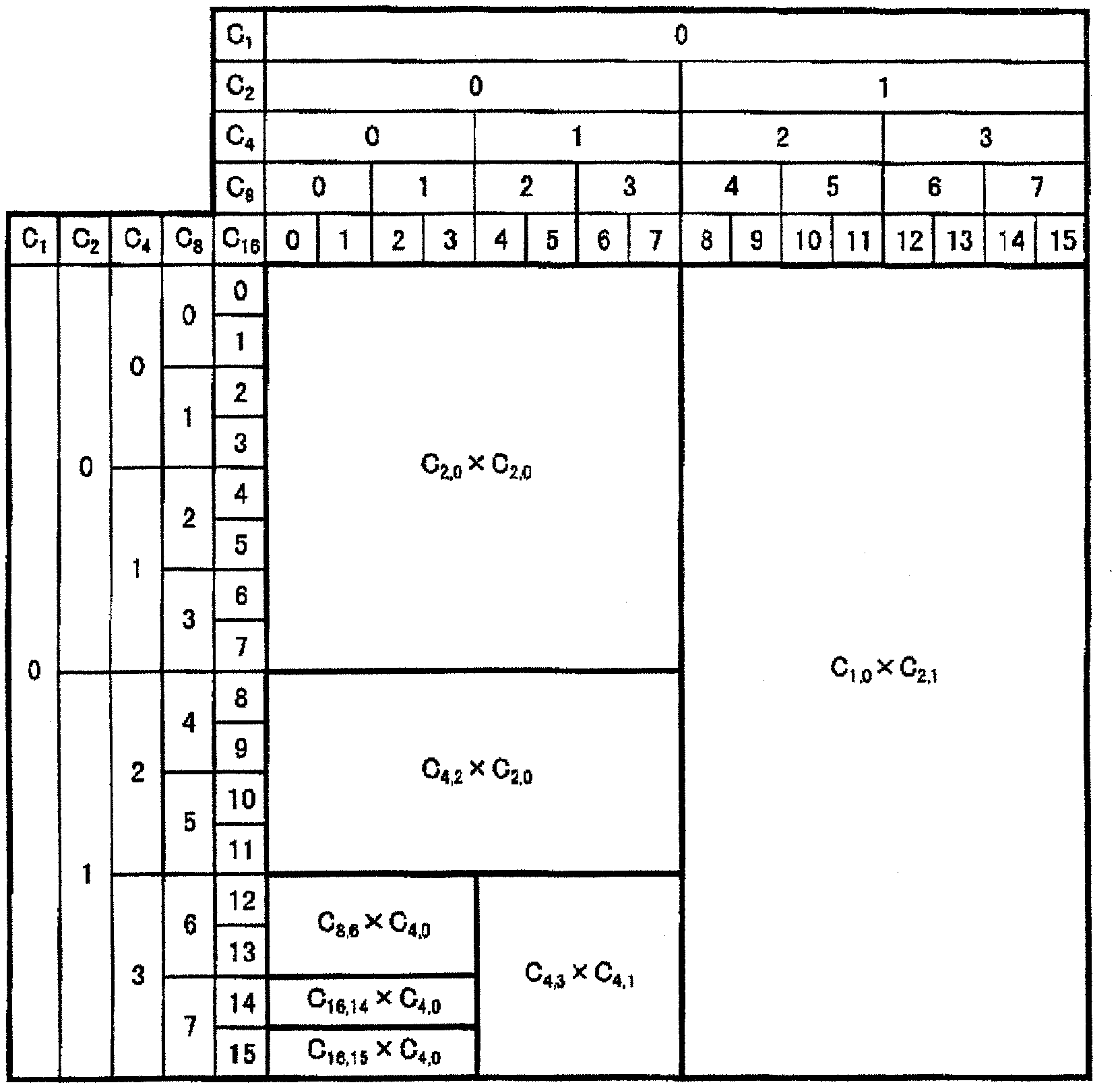
[0044] figure 1 It is a diagram explaining the code field of the two-dimensional spread code used in this embodiment.

[0045]In this code domain, the maximum spreading rate is 16 in both the time direction and the frequency direction. As the spreading code, a spreading code that is inversely spread with a spreading rate different from the original spreading rate (spreading rate used for spreading on the transmission side) or orthogonal in both the time direction and the frequency direction is used. This spreading code can be generated using an OVSF (Orthogonal Variable Spreading Factor, orthogonal variable spreading factor) code. in progress figure 1 The spreading code generated using the OVSF code will be specifically described before the description of .

[0046] It is well known that the OVSF code can sequentially generate codes whose code length is twice that of the following formula (1).

[0047] [Formula 1]

[0048] ...

no. 2 approach

[0112] In the first embodiment described above, the radio base station apparatus 60 estimates the state of the transmission path from the received signal. On the other hand, in the second embodiment, the state of the transmission path is notified from the mobile terminal to the radio base station apparatus.

[0113] Most of the configurations of the radio base station apparatus and the mobile terminal in the second embodiment are basically the same as those in the first embodiment. The action is also the same. Therefore, the same reference numerals are assigned to the parts that are basically the same as those in the first embodiment, and only the parts that are different from the first embodiment will be described.

[0114] Figure 16 It is a figure explaining the structure of the communication apparatus (radio base station apparatus) 60 of 2nd Embodiment.

[0115] As described above, in the second embodiment, the status of the transmission path is notified from the mobile...

no. 3 approach

[0123] In the first and second embodiments described above, data transmission between the mobile terminal 1200→radio base station apparatus 60 is performed without using the two-dimensional spread code. In the third embodiment, two-dimensional spreading codes are used in both bidirectional data transmissions.

[0124] Figure 18 It is a figure explaining the structure of the communication apparatus of 3rd Embodiment. The communication device is Figure 17 The illustrated communication device (mobile terminal) 1200 has a data transmission function using a two-dimensional spread code. Therefore pair with Figure 17 Substantially identical parts of the shown structures are labeled with the same reference numerals.

[0125] In the third embodiment, the spreading factor information output from the pilot despreading unit 1205 is directly input to the spreading code generating unit 1209 . The spreading code generation unit 1209 generates a spreading code specified by the input s...


PUM


Abstract

The invention provides a communication system comprising a sending device and a receiving device, wherein the sending device uses two-dimensional extended codes extending in a time direction and a frequency direction to send signals, and the receiving device is used for receiving the signals sent by the sending device; the sending device comprises a selection unit and a sending unit; the selection unit is used for selecting mutually-orthogonal extended codes in at least one direction of the time direction and the frequency direction; and the sending unit uses the selected extended codes to extend the signals and sends the signals, the extended codes can be segmented into more than two parts respectively, and the more than two parts are mutually orthogonal to the same part of the other selected extended codes in the at least one direction of the time direction and the frequency direction.

Description

[0001] This application is an invention patent application with the original application number 200480044600.2 (international application number: PCT / JP2004 / 018661, application date: December 14, 2004, invention name: spreading code distribution method, reverse spreading method, sending device, receiving device , communication devices, wireless base station devices and mobile terminal devices). technical field [0002] The present invention relates to a technique for transmitting and receiving data in units of channels using a two-dimensional spreading code that spreads in the time direction and the frequency direction. Background technique [0003] In recent years, in the field of mobile communication, OFDM- The CDMA method has attracted attention. The OFDM modulation method is a modulation method with high frequency utilization efficiency using a plurality of subcarriers orthogonal to each other, and the CDMA method is a modulation method using a spread spectrum communica...

Claims


Application Information

Patent Timeline
Patent Type & Authority Patents(China)
IPC IPC(8): H04J13/18H04L5/00
Inventor 下村刚史木村大矢野哲也
Owner FUJITSU LTD
Why Eureka
Try Eureka