Angle-scanning radar system

a radar system and angle detection technology, applied in the field of angle detection radar system, can solve problems such as inconvenient digital sampling, and achieve the effects of large visual range, easy digital sampling, and high degree of flexibility

Inactive Publication Date: 2006-10-10
ROBERT BOSCH GMBH
View PDF17 Cites 17 Cited by
  • Summary
  • Abstract
  • Description
  • Claims
  • Application Information

AI Technical Summary

Benefits of technology

[0006]The mixed baseband signal may easily be digitally sampled and digitally evaluated for further processing. The beam-shaping network may be made up of an HF structure, configuration or arrangement for splitting an oscillator transmitting signal among N paths with corresponding phase and / or amplitude weighting. This allows a multitude of directivity characteristics to be attained. Radar echos may be reliably assigned to objects in both the long range and the short range, using a separate changeover device for changing the antenna characteristic with regard to its angular width. This changeover device may advantageously be made up of micro-electromechanical switches or PIN diode switches. The switchover may advantageously be configured to be adaptive or to operate as a function of the velocity.
[0007]The phase and amplitude interference introduced by the beam-shaping network may be calibrated out in a simple manner. A Rotman lens or Butler matrix may advantageously be provided as a beam-shaping network. The radar system according to the present invention is suitable for motor-vehicle radar applications. An ACC system or a stop-and-go system may be set up by a simple changeover.

Problems solved by technology

If a plurality of targets is situated in one cell, incorrect angles may result.

Method used


Image

  • Angle-scanning radar system
  • Angle-scanning radar system

Examples


Embodiment Construction

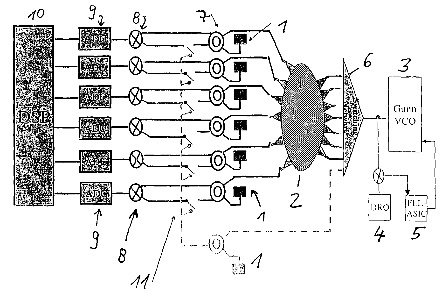
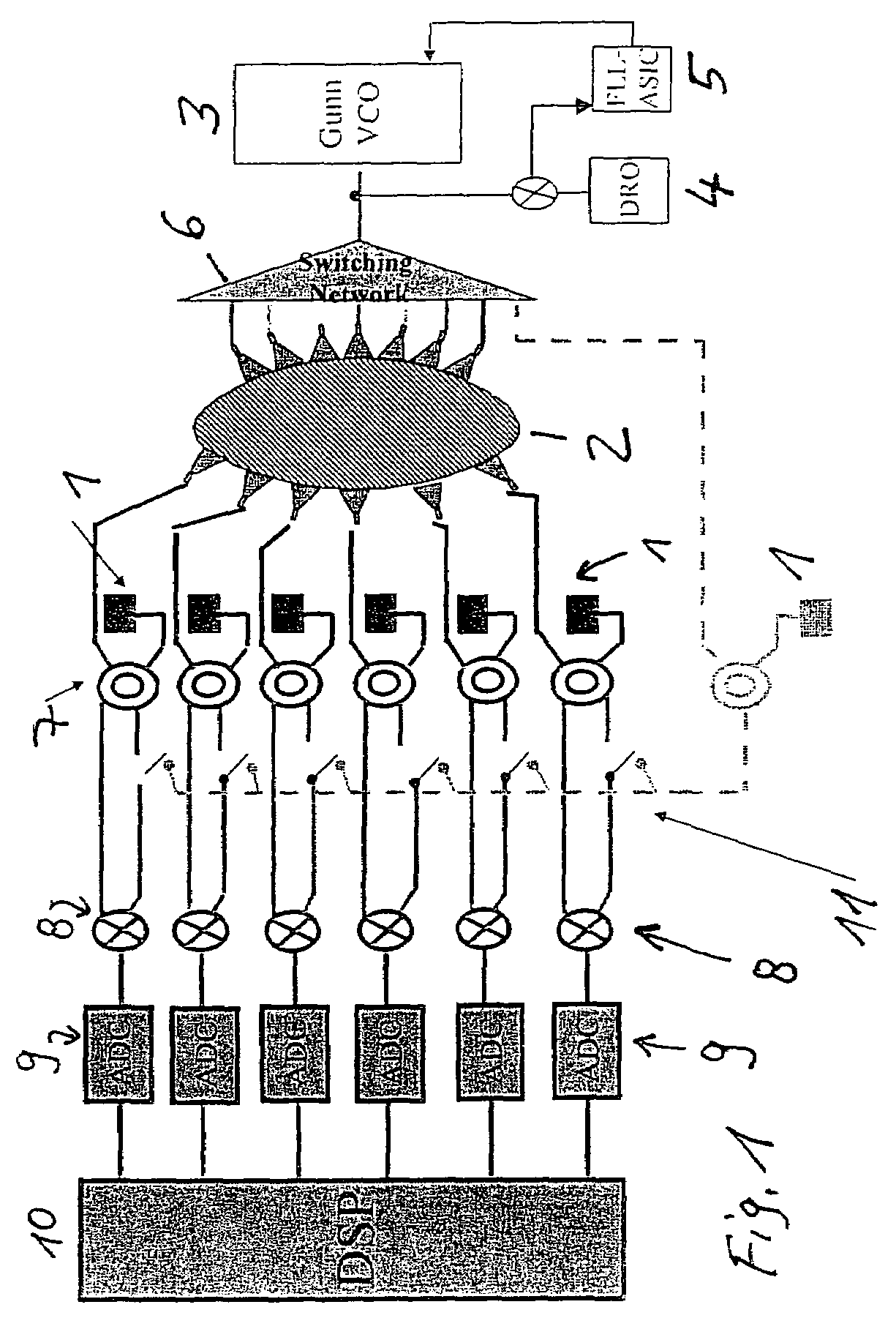
[0009]In the radar system according to an exemplary embodiment of the present invention, beam shaping and / or evaluation of spatial information simultaneously takes place in the transmitting and receiving directions. As shown in FIG. 1, a group antenna having N radiator elements 1 (in this case, N openings) is used in the radar system according to an exemplary embodiment of the present invention. An FMCW-radar principal is used as an exemplary embodiment. The radar system of the present invention may also be applied to other ones (principals), e.g. pulse radar.

[0010]The core part of the beam shaping in the transmission direction is an analog HF configuration as a beam-shaping network 2, e.g. in the form of a Butler matrix or Rotman lens of a phase-shifter network. The “one-dimensional” FMCW transmitting signal, which is conditioned, for example, by a Gunn VCO 3 having a carrier oscillator DRO 4 and FLL (frequency lock loop) ASIC 5, is transmitted by a switching network 6 to the input...


PUM


Abstract

An angle scanning radar system having a group antenna controlled via a beam-shaping network, a coupling device that allows the group antenna to be operated for both the transmitting and receiving directions, and a device to mix radar receiving signals with radar transmitting signals to form a mixed baseband signal, and to digitally evaluate the mixed baseband signal with regard to the solid-angle information.

Description

FIELD OF THE INVENTION[0001]The present invention relates to an angle-scanning radar system.BACKGROUND INFORMATION[0002]Radar systems for motor-vehicle applications, in particular driver-assistance systems such as ACC (Automatic Cruise Control) systems, which are based on the radar principle, may require a directionally resolved image of the vehicle surroundings (distance information / angle information) for evaluation. In determining the angle, current systems may operate according to monopulse methods, which are based on a comparison of amplitudes and phases of several reception directivity characteristics. These methods may achieve a sufficient resolution in a relatively narrow visual range, as long as only one target is situated in a distance / velocity cell. If a plurality of targets is situated in one cell, incorrect angles may result.[0003]A multibeam antenna system having a plurality of radiator elements, which are coupled to a beam-shaping network that takes the form of a Butle...

Claims


Application Information

Patent Timeline
Patent Type & Authority Patents(United States)
IPC IPC(8): G01S13/68G01S13/93H01Q3/26G01S7/03G01S7/282G01S13/02G01S13/42H01Q3/40H01Q25/00
CPCG01S7/032G01S7/282G01S13/426H01Q3/26H01Q3/40H01Q25/008G01S2013/0254G01S2013/0272
Inventor SCHOEBERL, THOMASFOCKE, THOMASMANSEN, DIRK
Owner ROBERT BOSCH GMBH
Why Eureka
Try Eureka