Heat treatment device and heat treatment method

A heat treatment method and a technology for processed objects, which are applied in heat treatment equipment, heat treatment process control, quenching devices, etc., can solve problems such as deformation, poor quality, and differences in cooling characteristics of processed objects, and achieve suppression of uneven temperature distribution and avoid deformation and the effect of hardness deviation

Inactive Publication Date: 2012-01-04
IHI CORP
View PDF6 Cites 6 Cited by
  • Summary
  • Abstract
  • Description
  • Claims
  • Application Information

AI Technical Summary

Problems solved by technology

[0007] If there is uneven distribution of spray density in the cooling chamber, the cooling characteristics will be different and there may be uneven temperature distribution on the object to be processed.
Also, when there are multiple objects to be processed, temperature differences may occur among the objects to be processed depending on the distribution of spray density
[0008] When uneven temperature distribution occurs on the object to be treated in this way, it may become a cause of deformation of the object to be processed, and when the object to be treated with uneven temperature distribution is used for quenching treatment, the object may be deformed. Can't get the same hardness
[0009] On the other hand, when a temperature difference occurs among a plurality of objects to be processed, there is a possibility of a quality difference among the objects to be processed, resulting in poor quality.

Method used


Image

  • Heat treatment device and heat treatment method
  • Heat treatment device and heat treatment method
  • Heat treatment device and heat treatment method

Examples


Embodiment Construction

[0034] Refer to the following Figure 1 to Figure 6 Embodiments of the heat treatment apparatus and the heat treatment method of the present invention will be described.

[0035] In addition, in each drawing used in the following description, the scale of each member is suitably changed in order to make each member a recognizable size.

[0036] In addition, in the present embodiment, an example of a multi-chamber vacuum heat treatment furnace (hereinafter simply referred to as “vacuum heat treatment furnace”) is shown as the heat treatment apparatus.

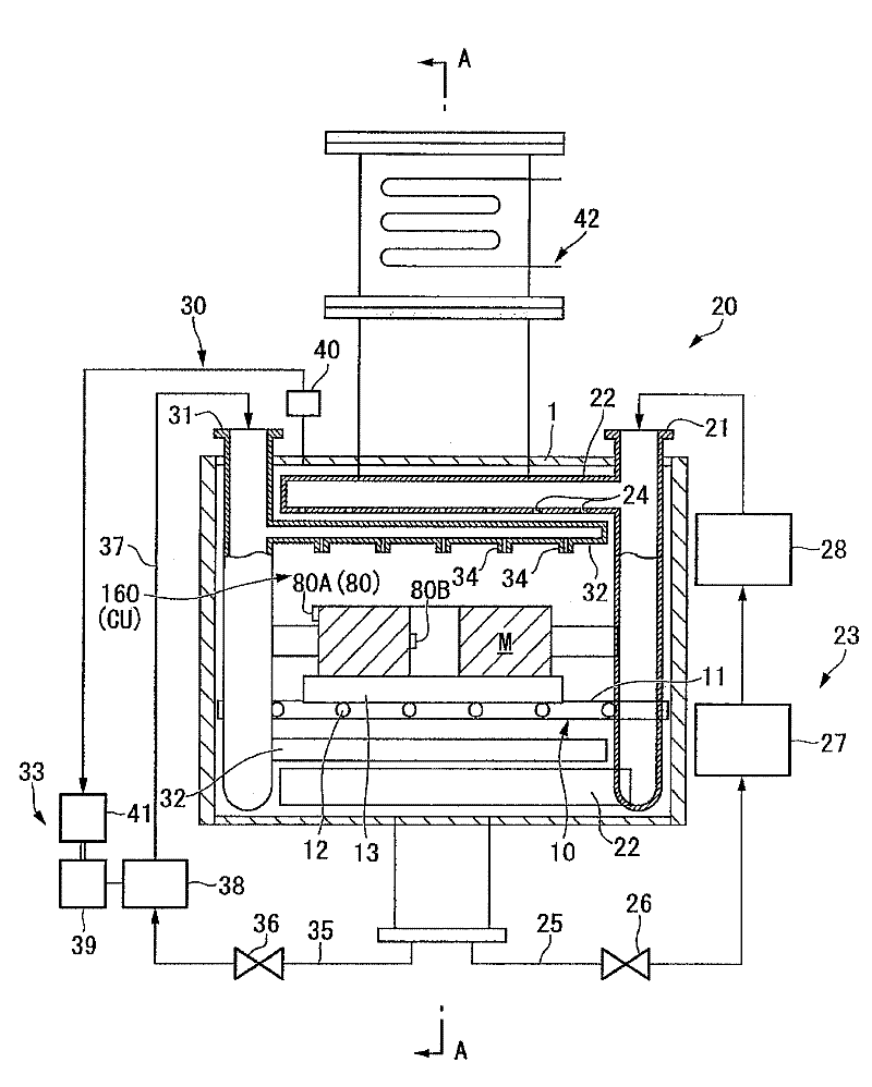
[0037] figure 1 It is an overall configuration diagram of the vacuum heat treatment furnace of this embodiment.

[0038] The vacuum heat treatment furnace (heat treatment device) 100 is a device for performing heat treatment on the object to be processed, and is arranged adjacently in sequence with a degassing chamber 110, a preheating chamber 120, a carburizing chamber 130, a diffusion chamber 140, a cooling chamber 150, and ...


PUM


Abstract

A heat treatment device and a heat treatment method which are configured so that the distribution of temperature in an object being treated is controlled during cooling operation. The heat treatment method has a cooling step for cooling, using a mist-like cooling liquid, an object being treated which has been heated. The method performs heat treatment by alternately repeating a first step (K1) for cooling the object at a first mist density and a second step (K2) for cooling the object at a second mist density lower than the first mist density.

Description

technical field [0001] The present invention relates to a heat treatment device and a heat treatment method, and is a heat treatment device that can be suitably used for treatments such as quenching of a treatment object, for example. [0002] This application claims priority based on Japanese Patent Application No. 2009-028900 filed in Japan on February 10, 2009, and Japanese Patent Application No. 2009-047227 filed in Japan on February 27, 2009, and uses the contents thereof here. Background technique [0003] In a heat treatment apparatus that heats and cools a metal material to be processed to perform a treatment such as quenching, when high-speed cooling is required, an oil-cooling type cooling device and a gas-cooling type cooling device have conventionally been used. In the cooling device of the above-mentioned oil cooling system, the cooling efficiency is excellent, but there is a problem that it is almost impossible to perform fine cooling control and the heat-treat...

Claims


Application Information

Patent Timeline
Patent Type & Authority Applications(China)
IPC IPC(8): C21D1/00C21D1/667
CPCF27B9/12C21D11/005C21D1/74C21D1/667F27B9/02C21D1/00
Inventor 胜俣和彦
Owner IHI CORP
Why Eureka
Try Eureka