Current transformer and current detection circuit and detection method

A technology of current detection circuit and current transformer, which is applied in the direction of inductors, measuring current/voltage, circuits, etc., can solve the problems of voltage spikes, reduce the power density of electrical devices, increase the distributed inductance of large current loops, etc., and achieve higher power effect of density

Inactive Publication Date: 2012-01-04
HUAWEI TECH CO LTD
View PDF3 Cites 4 Cited by
  • Summary
  • Abstract
  • Description
  • Claims
  • Application Information

AI Technical Summary

Problems solved by technology

[0004] In the process of realizing the current detection by the above-mentioned current transformer, the inventor found that there are at least the following problems in the prior art: the current transformer includes structural components such as primary windings, secondary windings, and magnetic cores, so it will occupy a large printed circuit board PCB layout area, thereby reducing the power density of electrical devices
At the same time, when the current transformer is connected in series with the large current loop, the distributed inductance of the large current loop will be increased, which will cause some voltage spikes, and at the same time bring electromagnetic compatibility (EMC, Electro Magnetic Compatibility) interference, affecting the high current loop. Reliable work of each component

Method used


Image

  • Current transformer and current detection circuit and detection method
  • Current transformer and current detection circuit and detection method
  • Current transformer and current detection circuit and detection method

Examples


Embodiment Construction

[0027] The current transformer, current detection circuit and detection method in the embodiments of the present invention will be described in detail below in conjunction with the accompanying drawings.

[0028] It should be clear that the described embodiments are only a part of the embodiments of the present invention, rather than all the embodiments. Based on the embodiments of the present invention, all other embodiments obtained by those of ordinary skill in the art without creative work shall fall within the protection scope of the present invention.

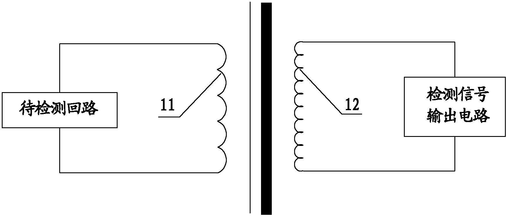
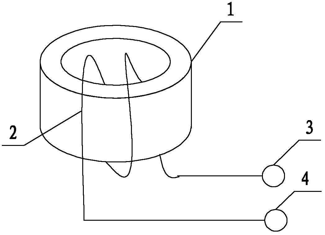
[0029] Such as figure 2 Shown is a specific embodiment of the current transformer of the present invention. In this embodiment, the current transformer includes a hollow magnetic core 1, and the hollow magnetic core 1 is used to cover the current-carrying conductor (such as image 3 The current-carrying conductor 5); A coil 2 is wound on the side wall of the hollow magnetic core 1 along the direction parallel to the central a...


PUM


Abstract

The invention discloses a current transformer, a current detection circuit and a detection method, which relate to the field of electric technique. The occupation space of a printed circuit board (PCB) is reduced and distribution inductance is decreased. The current transformer comprises a hollow magnetic core which is used for sleeving a current-carrying conductor needing to be detected in a loop to be detected. A coil is disposed on the side wall of the magnetic core along a direction parallel to the central shaft of the hollow magnetic core. The coil is provided with two access ends used for the electrical access of detection signal output electricity. The invention is used for current detection.

Description

Technical field [0001] The invention relates to the field of electrical technology, in particular to a current transformer, a current detection circuit and a detection method. Background technique [0002] In the field of electrical technology, in order to realize the control of output current and the protection of power devices, it is necessary to detect the current on some lines. Commonly used current detection techniques include resistance detection current, current transformer detection current and so on. The method of resistance detection of current is low in cost, simple in circuit, and fast in response, but when detecting a large current, the power loss of the resistance is large. Therefore, when a large current needs to be detected and low loss is required, a current transformer combined with a resistor is usually used to detect the current. [0003] The structure of traditional current transformer is like figure 1 As shown, the primary winding 11 and the secondary windin...

Claims


Application Information

Patent Timeline
Patent Type & Authority Applications(China)
IPC IPC(8): H01F38/28G01R15/18G01R19/00
CPCG01R15/183H01F38/30
Inventor 梁永涛
Owner HUAWEI TECH CO LTD
Why Eureka
Try Eureka