Radiation therapy system

A technology of radiotherapy and treatment heads, which is applied in the field of radiotherapy systems, can solve problems such as poor imaging effects of CT imaging devices, and achieve the effect of improving treatment accuracy

Inactive Publication Date: 2012-01-11
SHANGHAI SONGS LAB TECH DEV +1
View PDF2 Cites 8 Cited by
  • Summary
  • Abstract
  • Description
  • Claims
  • Application Information

AI Technical Summary

Problems solved by technology

[0003] The invention provides a radiotherapy system to solve the technical problem that the CT imaging device and the treatment head rotate at the same time in the existing radiotherapy system with a CT imaging device, resulting in poor imaging effect of the CT imaging device

Method used


Image

  • Radiation therapy system
  • Radiation therapy system
  • Radiation therapy system

Examples


Embodiment Construction

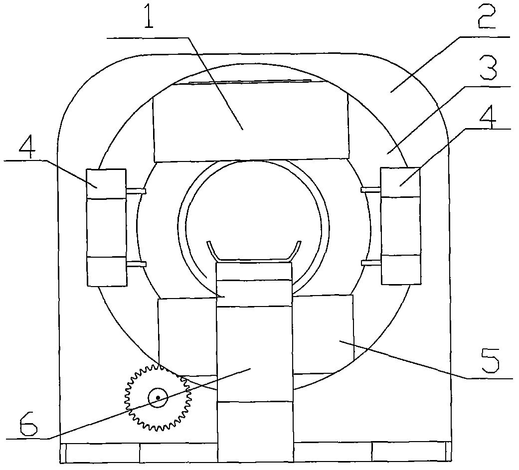
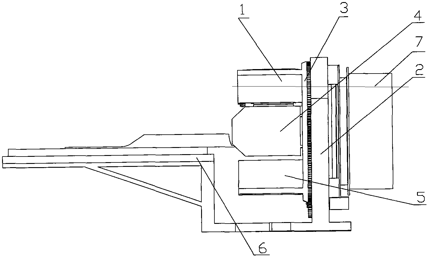
[0017] Such as Figure 1-4 As shown, a radiotherapy system includes a treatment head 1, a treatment head driving mechanism, a treatment couch 6, a CT imaging device 7, a common bracket 2 and a treatment head support frame 3, and a plurality of radiation sources are arranged on the treatment head, and a plurality of The radiation source is focused on a common focal point, one side of the treatment head support frame 3 is connected to the bearing of the common support 2, and the other side is connected to the treatment head 1; the CT imaging device 7 includes an X-ray tube, a CT support ring, a detector, a CT drive The mechanism, the signal conversion system, one side of the CT support ring are connected with the bearings of the shared bracket 2, the X-ray tube and the detector are relatively arranged on the other side of the CT support ring, the shared bracket 2, the treatment head support frame 2 and the CT support ring The middle hole is connected, and the treatment bed 6 can...


PUM


Abstract

The invention relates to a radiation therapy system, comprising a therapy head, a therapy head driving mechanism, a therapy bed, a shared bracket, a therapy head support frame and a CT (Captive Test) imaging device, wherein the CT imaging device comprises an X ray bulb tube, a CT supporting ring, a CT driving mechanism, a probe and a signal conversion system; one side of the therapy head support frame is connected with a shared bracket bearing, and the other side is connected with the therapy head; one side of the CT supporting ring is connected with the shared bracket bearing; the X ray bulb tube and the probe are oppositely arranged on the other side of the CT supporting ring; the middle holes of the shared bracket, the therapy head support frame and the CT supporting ring are communicated; the therapy bed can move in the middle holes of the shared bracket, the therapy head support frame and the CT supporting ring; the CT driving mechanism drives the CT supporting ring to rotate; and the therapy head driving mechanism drives the therapy head support frame to rotate. According to the radiation therapy system, the technical problem of poor imaging effect of the CT imaging device because the CT imaging device and the therapy head in the radiation therapy system with the traditional CT imaging device simultaneously rotate can be solved.

Description

technical field [0001] The present invention relates to a radiotherapy system. Background technique [0002] Existing radiotherapy systems include treatment heads, treatment head drive mechanisms and treatment couchs, and some also include CT imaging devices, but the CT imaging devices in existing radiotherapy systems with CT imaging devices rotate simultaneously with the treatment head, and Generally speaking, the rotation speed of the treatment head is very different from that of the CT imaging device. In order to ensure the treatment effect, the imaging effect of the CT imaging device is very poor. Contents of the invention [0003] The invention provides a radiotherapy system to solve the technical problem of poor imaging effect of the CT imaging device caused by the simultaneous rotation of the CT imaging device and the treatment head in the existing radiotherapy system with a CT imaging device. [0004] In order to solve the above technical problems, the technical s...

Claims


Application Information

Patent Timeline
Patent Type & Authority Applications(China)
IPC IPC(8): A61N5/10A61B6/03
Inventor 王翔宇郝建
Owner SHANGHAI SONGS LAB TECH DEV
Why Eureka
Try Eureka