
Imaging equipment control method and device, storage medium and processor

A technology of imaging equipment and control method, applied in image data processing, instrument, image enhancement and other directions, can solve problems such as poor imaging effect

Pending Publication Date: 2020-05-15
STATE GRID BEIJING ELECTRIC POWER +1
View PDF7 Cites 0 Cited by
  • Summary
  • Abstract
  • Description
  • Claims
  • Application Information

AI Technical Summary

Problems solved by technology

[0005] Embodiments of the present invention provide a control method, device, storage medium, and processor for an imaging device, so as to at least solve the technical problem of poor imaging effect caused by a single imaging method in the related art

Method used


Image

  • Imaging equipment control method and device, storage medium and processor
  • Imaging equipment control method and device, storage medium and processor
  • Imaging equipment control method and device, storage medium and processor

Examples


Embodiment 1

[0023] According to an embodiment of the present invention, an embodiment of a method for controlling an imaging device is provided. It should be noted that the steps shown in the flowcharts of the accompanying drawings can be executed in a computer system such as a set of computer-executable instructions, and , although a logical order is shown in the flowcharts, in some cases the steps shown or described may be performed in an order different from that shown or described herein.

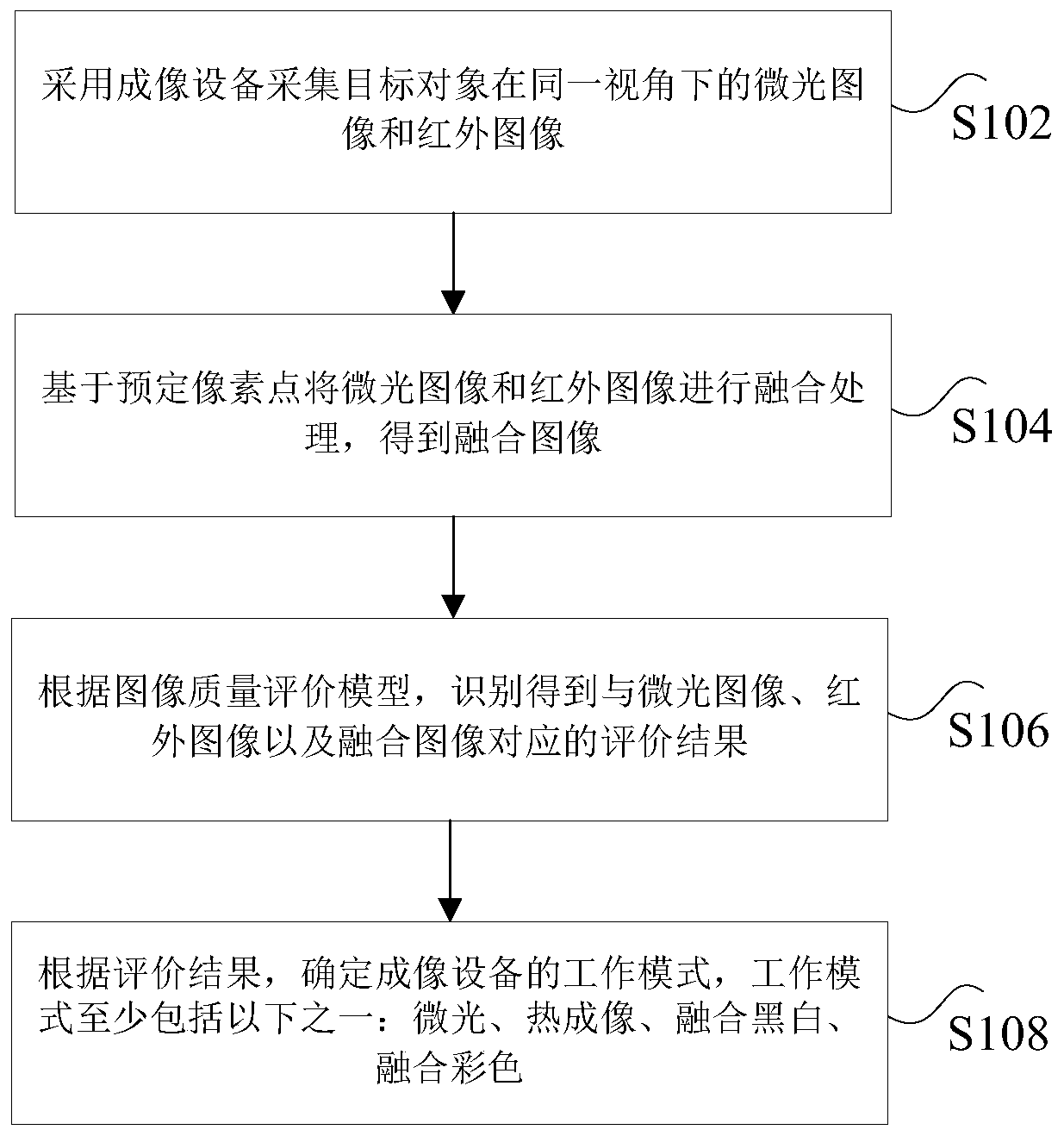
[0024] figure 1 is a flowchart of a control method of an imaging device according to an embodiment of the present invention, such as figure 1 As shown, the control method of the imaging device includes the following steps:

[0025] Step S102, using an imaging device to collect low-light images and infrared images of the target object under the same viewing angle;

[0026] The imaging equipment mentioned above is a fusion telescope, low-light night vision equipment with an infrared thermal imager,...

Embodiment 2

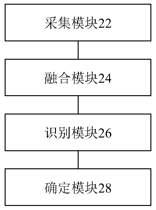
[0054] According to another aspect of the embodiments of the present invention, an embodiment of an apparatus for executing the method for controlling the imaging device in Embodiment 1 above is also provided, figure 2 is a schematic diagram of a control device of an imaging device according to an embodiment of the present invention, such as figure 2 As shown, the control device of the imaging device includes: an acquisition module 22 , a fusion module 24 , an identification module 26 and a determination module 28 . The control device of the image forming apparatus will be described in detail below.

[0055] The collection module 22 is configured to use an imaging device to collect low-light images and infrared images of the target object under the same viewing angle;

[0056] The fusion module 24 is connected to the acquisition module 22, and is used to fuse the low-light image and the infrared image based on predetermined pixel points to obtain a fusion image;

[0057] T...

Embodiment 3

[0067] According to another aspect of the embodiments of the present invention, there is also provided a storage medium, the storage medium includes a stored program, wherein when the program is running, the device where the storage medium is located is controlled to execute any one of the methods for controlling the imaging device described above.


PUM


Abstract

The invention discloses a control method and device of imaging equipment, a storage medium and a processor. The method comprises the following steps: acquiring a low-light image and an infrared imageof a target object at the same visual angle by adopting imaging equipment; performing fusion processing on the low-light image and the infrared image based on predetermined pixel points to obtain a fused image; according to the image quality evaluation model, performing identification to obtain evaluation results corresponding to the low-light-level image, the infrared image and the fusion image;according to the evaluation result, determining the working mode of the imaging equipment, and the working mode at least comprises one of low light, thermal imaging, black and white fusion and color fusion. According to the method, the technical problem of poor imaging effect caused by a single imaging mode in related technologies is solved.

Description

technical field [0001] The present invention relates to the technical field of imaging equipment control, in particular, to a control method, device, storage medium and processor of an imaging equipment. Background technique [0002] With the construction and development of cities, undergrounding of transmission and distribution line facilities is particularly important in improving urban environment and strengthening urban disaster prevention and safety. At present, power lines mostly use underground transmission and distribution lines, and are laid by slotting, pipe jacking, shallow buried excavation, and shield tunneling. The working scope of the power tunnel project at the present stage is mainly the underground area. When carrying out some major construction operations, night work is essential. Since nighttime work is significantly different from normal work, it is mainly reflected in the fact that the working environment faced by nighttime work is mostly dark, and th...

Claims


Application Information

Patent Timeline
IPC IPC(8): G06T5/50G06T7/00
CPCG06T5/50G06T7/0002G06T2207/10004G06T2207/10048G06T2207/20081G06T2207/30168
Inventor 林超王磊赵鲲翔张伍伟陈见宇古远明
Owner STATE GRID BEIJING ELECTRIC POWER
Learn More