Rolling mill flying scissor blade cooling method and cooling device thereof

A cooling method and a cooling device technology, which are applied in the direction of shearing devices, shearing machine accessories, metal processing machinery parts, etc., can solve problems that affect the smooth progress of production, increase equipment operating costs, and affect the yield of rolled products, etc., to achieve Improve life and shear quality, reduce spare parts cost, good shear quality effect

Active Publication Date: 2012-01-11
SHAOGUAN IRON & STEEL GROUP CORP GUANGDONG PROV +1
View PDF5 Cites 7 Cited by
  • Summary
  • Abstract
  • Description
  • Claims
  • Application Information

AI Technical Summary

Problems solved by technology

When the 1# flying shear is continuously shearing, the temperature of the cutter shaft and the crankshaft is as high as 300°C, causing the grease in the copper sleeve of the sliding bearing to leak and overflow due to the high temperature, resulting in poor lubrication of the copper sleeve, rapid wear, and gradual increase in the bearing clearance , causing the 1# flying shear to lose its efficacy, resulting in accidents such as continuous bending of the billet; and in order to ensure the normal operation and product quality of the 1# flying shear and the follow-up, the copper bushing of the sliding bearing of the knife shaft had to be replaced.
[0008] It can be seen from the above that the traditional natural cooling method of 1# flying shear has the following series of disadvantages: not only affects the smooth progress of production, causes production misproduction, affects the yield of rolled products, but also increases the equipment operating cost

Method used


Image

  • Rolling mill flying scissor blade cooling method and cooling device thereof
  • Rolling mill flying scissor blade cooling method and cooling device thereof
  • Rolling mill flying scissor blade cooling method and cooling device thereof

Examples


Embodiment Construction

[0041] Method example:

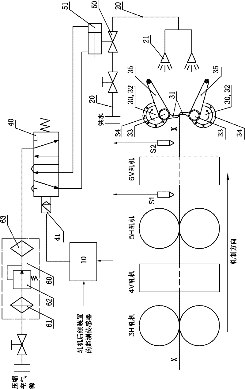
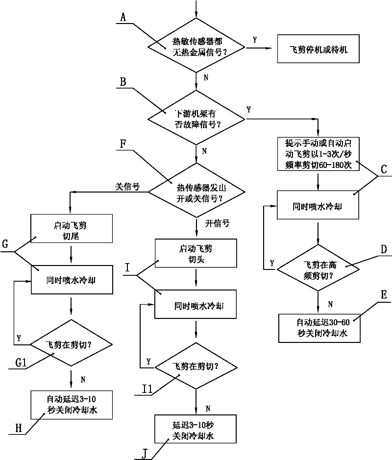
[0042] like figure 1 , which is a schematic flow diagram of an embodiment of the cooling method for rolling mill flying shear blades according to the present invention. In this embodiment of the method, a thermal sensor is set to detect the movement and position of the wire on the way to the flying shear blade, and the detection signal is transmitted to the control circuit, and includes the following steps:

[0043] A. When the thermal sensor sends out a low-level or zero-voltage detection signal without change for more than 3 minutes, and the control circuit interprets that the hot metal does not exist, the flying shears and their blades stop or stand by; when the thermal sensor sends out a signal Different from the above process, the control circuit interprets that there is hot metal and turns to step B;

[0044] B. Detect whether there is a fault signal on the frame downstream of the flying shear blade? If there is a fault signal, go to step C, i...


PUM

PropertyMeasurementUnit
diameteraaaaaaaaaa

Abstract

The invention relates to a rolling mill flying scissor blade cooling method and a cooling device thereof. In the cooling method, a heat-sensitive sensor is arranged to detect the movement and the position of wire stocks in the process in which the wire stocks are transported to a flying scissor blade, and a detection signal is transmitted to a control circuit. The method comprises the following steps: sending out a hot metal existence/non-existence detection signal and controlling the flying scissor blade to halt or stand by; or spraying water to cool the flying scissor blade and automatically delaying the close of sprayed cooling water. According to the cooling method and the device thereof disclosed by the invention, on the premise of saving water and preventing water from splashing andinfiltering into a bearing oil seal, a more effective water cooling mode is adopted to cool the flying scissor blade, so the temperatures of the flying scissor blade as well as a cutter shaft and a crankshaft thereof can be greatly reduced, the shearing quality of flying scissors is improved, the overall working life of the blade and the flying scissors is prolonged, and the failure rate of the whole device is reduced.

Description

technical field [0001] The present invention relates to a metallurgical process device, more specifically, the present invention relates to a process device and a process method of a metallurgical rolling mill. Background technique [0002] As an important device of metallurgical technology, in order to meet the product requirements and ensure the continuous and normal production process of wire rods, the high-speed wire rod rolling mill is usually installed after the 6# rolling mill in the rough rolling (V or H rolling direction) and the 7# rolling mill in the middle rolling. Before, equipped with crank-type flying shears with blades (usually abbreviated as 1# flying shears), in order to implement important functions such as cutting the head and tail of the wire rod, and preventing subsequent accidents and breaking accidents; the crank start-stop type 1 The performance parameters of #flying shears can usually reach: the maximum shearing section is 5026mm2 (diameter 80mm), t...

Claims


Application Information

Patent Timeline
Patent Type & Authority Applications(China)
IPC IPC(8): B23D33/00B23Q11/10B23Q17/09
Inventor 蒋弦弋郭继亮谭龙海陈帆陈听雨王晋国
Owner SHAOGUAN IRON & STEEL GROUP CORP GUANGDONG PROV
Why Eureka
Try Eureka