Roof luggage rack for automobile

A technology for luggage racks and automobiles, which is applied to vehicle parts, additional accessories, transportation and packaging, etc. It can solve problems such as unreliable connection between crossbars and sidebars, inability to adjust the distance between front and rear crossbars, and inability to adjust luggage loads, etc., to achieve Improve the overall load-carrying performance, ample sidebar adaptation performance, and the effect of force balance

Active Publication Date: 2012-01-11
广东君辉汽车用品有限公司
View PDF5 Cites 6 Cited by
  • Summary
  • Abstract
  • Description
  • Claims
  • Application Information

AI Technical Summary

Problems solved by technology

[0002] The structure of the common car roof luggage rack usually uses screws to fix the cross bars on the two side bars. This fixed connection structure cannot adjust the distance between the front and rear cross bars, so that the luggage loading capacity cannot be adjusted. When installing and removing the cross bar, the screws must be unscrewed. During the long-term use of this connection method, the screws may be loosened due to the vibration of the car running, making the connection between the cross bar and the side bar unreliable; when the cross bar and the side bar are required When the rod moves relatively, it will wear the side rod, and the length of the cross rod of this structure is fixed, so the adaptability is low

Method used


Image

  • Roof luggage rack for automobile
  • Roof luggage rack for automobile
  • Roof luggage rack for automobile

Examples


Embodiment Construction

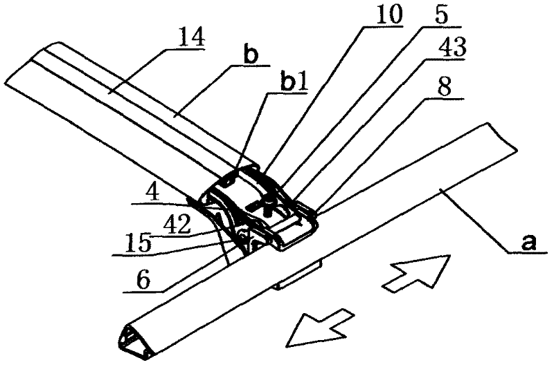
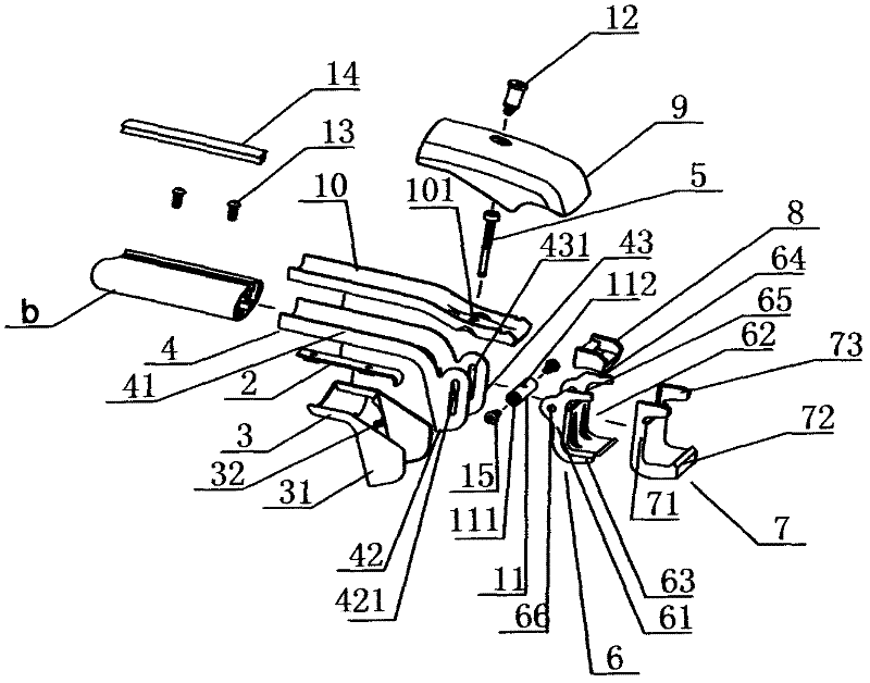
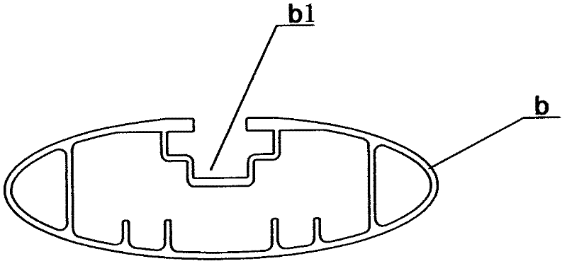
[0020] Such as figure 1 , 2 , shown in 4, the present invention is a kind of car roof luggage rack, comprises the two side bars a that are arranged on the two longitudinal sides of the car roof and two cross bars b that are arranged between the two side bars a, two cross bars b and A movable adjustment structure is provided between the rods a on both sides, and the movable adjustment structure includes a fixed bracket 4, a movable bracket 6 and a compression bracket 10, wherein one end of the fixed bracket 4 is sleeved and fixed in the lumen of the cross bar b, The other end of the fixed bracket 4 is pivotally connected to the movable bracket 6; one end of the movable bracket 6 is pivotally connected to the fixed bracket 4 through a screw sleeve 11 and two hexagon socket screws 15, and the other end of the movable bracket 6 is provided with a C-shaped groove connected with the side bar a 62;

[0021] Such as figure 2 , 6 As shown, the middle part of the screw sleeve 11 tr...


PUM


Abstract

The invention relates to a roof luggage rack for an automobile, which comprises two side rods, two transverse rods, a fixed support frame, a movable support frame and a compressed support frame, wherein one end of the fixed support frame is sheathed and fixed in pipe cavities of the transverse rods, the other end of the fixed support frame is pivoted with the movable support frame, one end of themovable support frame is pivoted on the fixed support frame through a screw sleeve and two socket hexagon screws, the other end of the movable support frame is provided with a C-shaped groove connected with the side rods, a fastening screw hole is arranged in the middle of the screw sleeve in a way of transversely penetrating a sleeve body, a through hole is arranged in the compressed support frame, one end of the compressed support frame is sheathed and fixed in the pipe cavities of the transverse rods, and the other end of the compressed support frame is screwed into the fastening screw hole arranged in the middle part of the screw sleeve after passing through the through hole through a socket hexagon fastening bolt for tightly compressing the side rods. The lower part of the fixed support frame is sealed and decorated through a plastic lower case, the upper part of the compressed support frame is sealed and decorated through a plastic upper case. The extension and contraction of the transverse rods and the relative position of the transverse rods on the side rods can be regulated, and the vehicle load capacity is improved. The transverse rods can be conveniently taken down. An upper rubber pad and a lower rubber pad are adopted, and the buffer effect is realized.

Description

technical field [0001] The invention relates to the field of automobile supplies, in particular to an automobile roof luggage rack. Background technique [0002] The structure of the common car roof luggage rack usually uses screws to fix the cross bars on the two side bars. This fixed connection structure cannot adjust the distance between the front and rear cross bars, so that the luggage loading capacity cannot be adjusted. When installing and removing the cross bar, the screws must be unscrewed. During the long-term use of this connection method, the screws may be loosened due to the vibration of the car running, making the connection between the cross bar and the side bar unreliable; when the cross bar and the side bar are required When the bar moves relatively, the side bar will be worn, and the length of the cross bar of this structure is fixed, so the adaptability is low. Contents of the invention [0003] The purpose of the present invention is to address the abo...

Claims


Application Information

Patent Timeline
Patent Type & Authority Applications(China)
IPC IPC(8): B60R9/045B60R9/058
Inventor 周用强
Owner 广东君辉汽车用品有限公司
Why Eureka
Try Eureka