Hydraulic clutch and method for determining an adaptive clutch fill volume or return spring pressure

A technology of hydraulic clutch and filling volume, which is applied in clutches, fluid-driven clutches, non-mechanical-driven clutches, etc. It can solve problems such as expensive components and complex technologies, and achieve the effects of cost reduction and improvement, quality reduction and saving, and applicability improvement

Active Publication Date: 2012-01-11
GM GLOBAL TECH OPERATIONS LLC
View PDF6 Cites 9 Cited by
  • Summary
  • Abstract
  • Description
  • Claims
  • Application Information

AI Technical Summary

Problems solved by technology

However, the disclosed method involves expensive ...

Method used


Image

  • Hydraulic clutch and method for determining an adaptive clutch fill volume or return spring pressure
  • Hydraulic clutch and method for determining an adaptive clutch fill volume or return spring pressure
  • Hydraulic clutch and method for determining an adaptive clutch fill volume or return spring pressure

Examples


Embodiment Construction

[0193] In the following description, the embodiments are described in detail. It will be apparent to those skilled in the art that the embodiment may be practiced without these details. Figure 1-15 Components with the same reference number are included. The description of these components is hereby incorporated by reference.

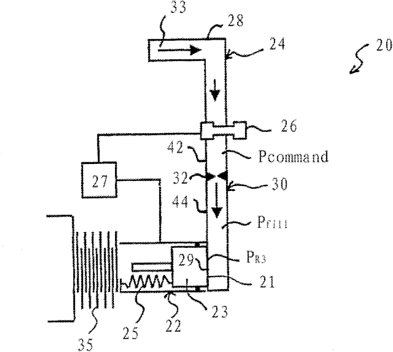
[0194] figure 1 A hydraulic clutch assembly 20 is shown including a hydraulic clutch 22 , a fill line 24 and a clutch fill regulator valve 26 . The hydraulic clutch 22 is connected to a first end 21 of a fill conduit 24 filled with hydraulic oil 33 . A regulator valve 26 divides the fill conduit 24 into an upstream tube 28 and a downstream tube 30 . In other words, the upstream pipe 28 and the downstream pipe 30 are joined together via the regulator valve 26 . Downstream conduit 28 also connects regulator valve 26 to hydraulic clutch 22 .

[0195] Hydraulic clutch 22 includes two arrays of piston 23 , return spring 25 and rotating friction element...


PUM


Abstract

The invention relates to a hydraulic clutch and a method for determining an adaptive clutch fill volume or return spring pressure. The application discloses a method for learning a characteristic filling volume of a hydraulic clutch (22). The method comprises iterative steps of applying a pressure pulse to the hydraulic clutch (22) when the clutch is in a disengaged state and determining an inflection event at an input or at an output of a torque path in which the hydraulic clutch (22) is situated. A characteristic filling volume of the hydraulic clutch (22) is derived from the determined inflection event. Furthermore, the application discloses a method for learning a characteristic return spring pressure of the hydraulic clutch (22), for engaging the hydraulic clutch (22) and corresponding devices for carrying out the methods according to the application.

Description

technical field [0001] The invention relates to a hydraulic clutch. It also relates to a method for determining an adaptive clutch fill volume of the hydraulic clutch. Background technique [0002] Hydraulic clutches include hydraulically actuated friction elements. The friction element generally includes a housing, a piston, and a clutch apply cavity defined between the housing and one side of the piston. The hydraulic clutch may also include a plurality of alternating metal plates and discs of friction material on the other side of the piston. Hydraulic oil is pumped into and out of the cavity for engaging and disengaging the hydraulic clutch. In a vehicle power train, a hydraulic clutch may be positioned between the crankshaft and the transmission for transferring drive torque from the crankshaft to the transmission. In the case of an automotive transmission, the gearbox itself may also include hydraulic clutches for actuating gears and thus for shifting gears. [00...

Claims


Application Information

Patent Timeline
IPC IPC(8): F16D25/12F16D25/10F16H47/00
CPCF16D2500/30818F16D48/066F16D2500/1026F16D2500/5018F16D48/02F16D48/06
Inventor 摩根.波斯蒂克马克.兰伯特埃里克.达拉伊斯伊曼纽尔.霍夫纳萨尼尔.维尔克
Owner GM GLOBAL TECH OPERATIONS LLC
Why Eureka
Try Eureka