Optical Digital-to-Analog Conversion

A digital-to-analog converter, optical technology, used in digital-to-analog conversion. Fields, can solve problems such as non-integrability

Inactive Publication Date: 2016-01-06
TELEFON AB LM ERICSSON (PUBL)
View PDF2 Cites 0 Cited by
  • Summary
  • Abstract
  • Description
  • Claims
  • Application Information

AI Technical Summary

Problems solved by technology

However, this approach requires a separate detection signal whose generation is not integrated with the rest of the DAC photonic circuitry

Method used


Image

  • Optical Digital-to-Analog Conversion
  • Optical Digital-to-Analog Conversion
  • Optical Digital-to-Analog Conversion

Examples


Embodiment Construction

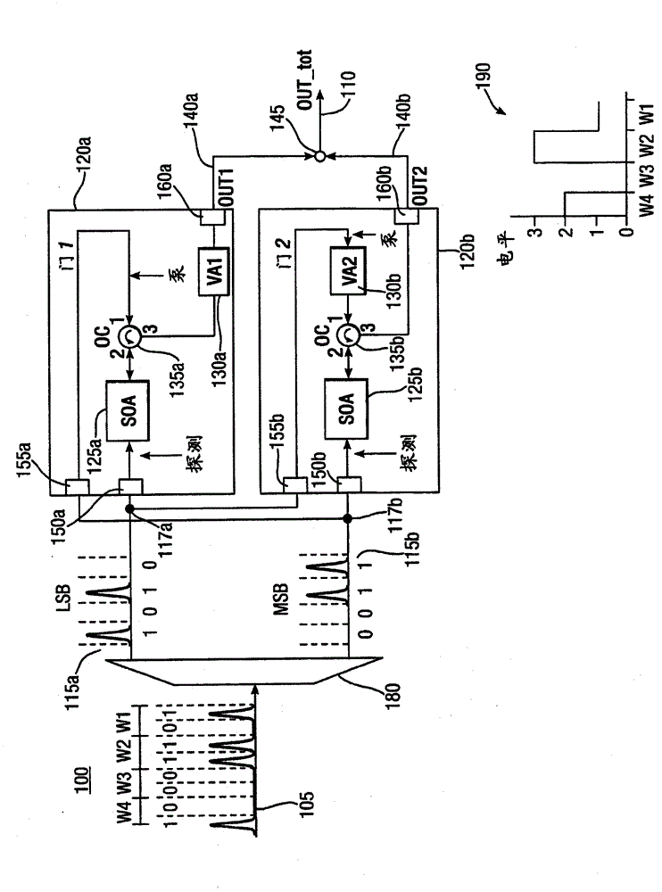
[0020] figure 1 A 2-bit digital-to-analog converter (DAC) is shown, arranged to receive a 2-bit digital optical signal, and to process this 2-bit digital optical signal to generate an analog optical signal. DAC 100 includes two optical processing gates 120 a and 120 b that receive input from serial-to-parallel converter 180 and output to combiner 145 . Optical processing gates, serial-to-parallel converters and combiners are photonic circuits arranged to process incoming optical digital signals 105 into analog optical signals 190 in the optical domain. The optical digital signal comprises a sequence of optical pulses (wl, w2, w3, w4) arranged in 2-bit words. Each 2-bit word is converted by DAC 100 to one of multiple output levels of analog signal 190 . It can be seen that word w1 (01) corresponds to analog output level 1, w2 (11) corresponds to level 3, w3 (00) corresponds to level 0, and w4 corresponds to level 2, where the binary words are represented by Gray Code represe...


PUM


Abstract

The present invention relates to Digital-to-Analog conversion in the optical or photonic domain. The present invention provides a digital-to-analog converter (DAC) (100) arranged to receive an N-bit digital optical signal (105) and to process the N-bit digital optical signal to generate an analog optical signal (110). The DAC comprises a photonic circuit (120a, 120b) arranged to adjust the amplitude of each bit of the N-bit digital optical signal dependent on the amplitudes of at least one of the other bits of the N-bit digital optical signal. The amplitudes are adjusted using a non-linear optical effect in order to generate respective outputs for each bit. The DAC also comprises a photonic combiner (145) arranged to combine the outputs for each bit to generate the analog output signal (110).

Description

technical field [0001] The invention relates to digital-to-analog conversion in the field of optics or photonics. Background technique [0002] Although digital-to-analog conversion (DAC) is well known in the electrical field, little attention has so far been paid to DACs in the optical or photonic fields. The use of an all-optical DAC can be used to implement ultra-fast signal processing functions such as pattern recognition for header extraction techniques, amplitude multiplexing (alllevel conversion) for improved spectral efficiency or tag / payload encoding techniques, and waveform generation for radar and display applications. Existing photonic DAC technology utilizes coherent optical summing, but this requires accurate control of the phase of the signals to be summed or combined. A further technique uses a nonlinear optical loop mirror (NOLM) interferometer switch and a probe signal containing optical pulses to generate four amplitude shift keyed optical signals from t...

Claims


Application Information

Patent Timeline
Patent Type & Authority Patents(China)
IPC IPC(8): G02F7/00G02F1/35
CPCG02F1/3515G02F7/00G02F2203/70
Inventor C·波奇L·波蒂A·博戈尼
Owner TELEFON AB LM ERICSSON (PUBL)
Why Eureka
Try Eureka