
Clamping type safety lock with clamping groove upper pins

A safety lock and tumbler technology, applied in the field of locks, can solve problems such as difficult mass production, complex manufacturing process, and difficult technology to unlock, and achieve the effects of easy mass production, simple manufacturing process, and simple structure

Inactive Publication Date: 2013-06-19
杜良民 +1
View PDF5 Cites 0 Cited by
  • Summary
  • Abstract
  • Description
  • Claims
  • Application Information

AI Technical Summary

Problems solved by technology

Ordinary pin tumbler sleeve locks are widely used due to their simple structure, low cost, and low price, but they have the fatal weakness of being easy to unlock technically; although complex pin tumbler sleeve locks have the advantage of being difficult to unlock technically, there are The disadvantages of complex manufacturing process, high cost and difficulty in mass production

Method used


Image

  • Clamping type safety lock with clamping groove upper pins
  • Clamping type safety lock with clamping groove upper pins
  • Clamping type safety lock with clamping groove upper pins

Examples


Embodiment Construction

[0019] The present invention will be described in further detail below in conjunction with the accompanying drawings and embodiments, but these embodiments should not be construed as limiting the present invention.

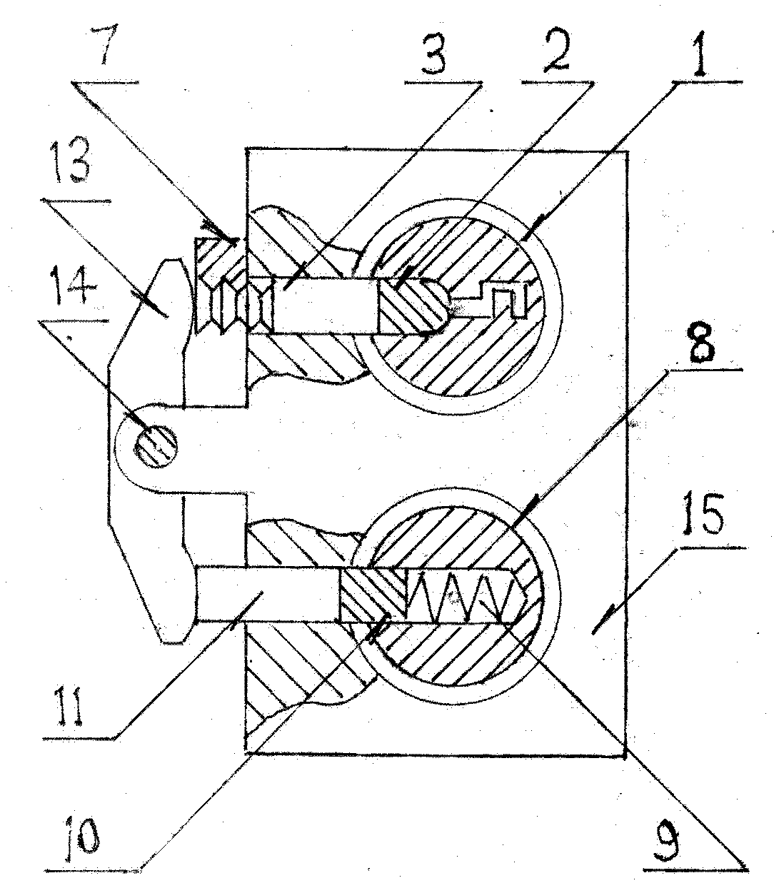
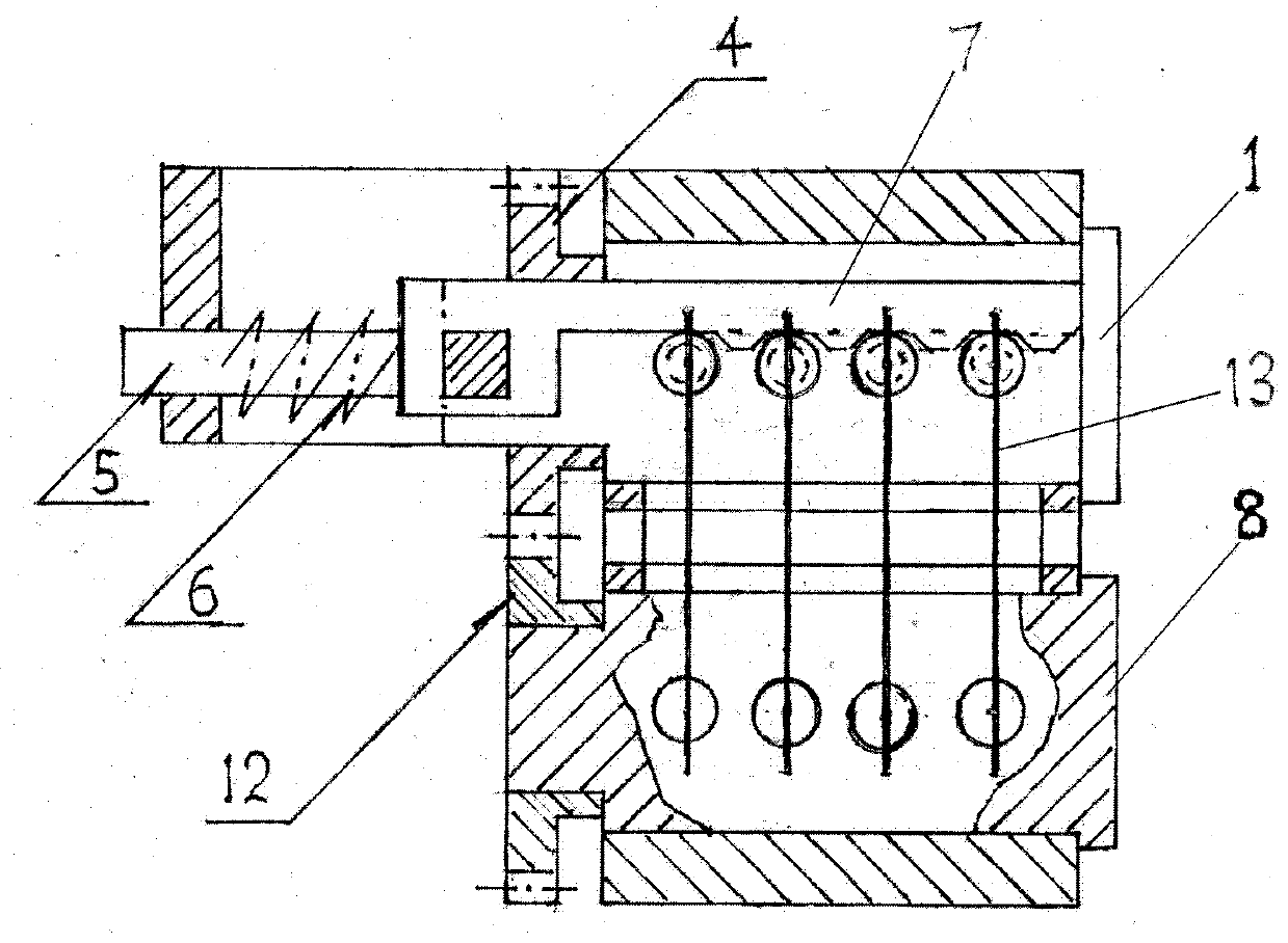
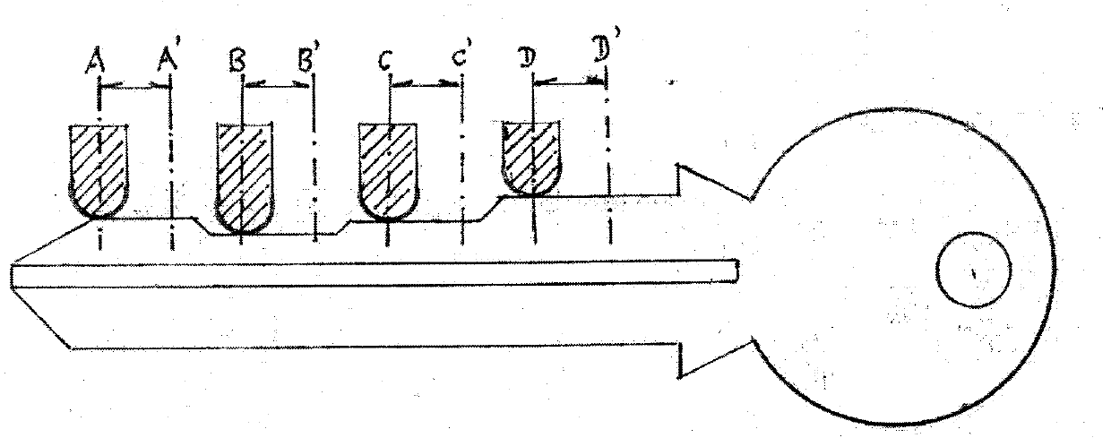
[0020] This embodiment provides a pin-type safety lock on a card slot, including: a self-locking system, a locking system and a self-locking compensation system. 2 and a lock body 15; the locking system is composed of pins 3 on the slot, a slot plate 7 and an L-shaped latch 5 with a compression spring 6 on the horizontal part, the pins 3 on the slot and the plate on the slot 7 are respectively movably installed on the lock body 15, the upper marble 3 of the card slot is in contact with the end surface of the lower marble 2 of the ball head, the vertical part of the card bolt 5 is connected with the described card slot plate 7, and the horizontal part of the card bolt 5 The end is clamped on the lock body 15, and the end of the main lock core 1 is provided with an ...


PUM


Abstract

The invention provides a clamping type safety lock with clamping groove upper pins. The clamping type safety lock with clamping groove upper pins comprises a self-locking system, a clamping locking system and a self-locking compensating system, wherein the self-locking system comprises a main lock core, ball-head lower pins and a lock body; the clamping locking system comprises clamping groove upper pins, a clamping groove plate and a clamping bolt, wherein the clamping groove upper pins and the clamping groove plate are arranged on the lock body, the clamping groove upper pins contact the ball-head lower pins, the vertical part of the clamping bolt is connected with the clamping groove plate, the tail end of the horizontal part of the clamping bolt is clamped on the lock body, the tail end of the main lock core is provided with an open groove, and the bent part of the clamping bolt is clamped in the open groove; and the self-locking compensating system comprises an auxiliary lock core with a driven gear, flat-head lower pins, flat-head upper pins and a transmission device, wherein the auxiliary lock core and the flat-head upper pins are arranged on the lock body, the transmissiondevice is fixed on the lock body, the two ends of the transmission device are respectively in contact with the clamping groove upper pins and the flat-head upper pins, the flat-head lower pins are arranged in the auxiliary lock core in a pressed manner through pin compressed springs, the flat-head upper pins and the flat-head lower pins are in contact, and the driven gear is meshed with a drivinggear. The invention has the advantage of simple structure and is applicable to locks.

Description

technical field [0001] The invention belongs to locks, in particular to a pin-type safety lock on a card slot. Background technique [0002] The current structural forms of pin-turning core sleeve locks include: ordinary pin-turning core sleeve locks and complex pin-turning core sleeve locks. Ordinary pin tumbler sleeve locks are widely used due to their simple structure, low cost, and low price, but they have the fatal weakness of being easy to unlock technically; although complex pin tumbler sleeve locks have the advantage of being difficult to unlock technically, there are The manufacturing process is complicated, the cost is high, and it is difficult to form mass production. Contents of the invention [0003] The object of the present invention is to overcome the disadvantages of the above-mentioned background technology and provide a pin-on-slot safety lock with simple structure, low cost and easy mass production. [0004] In order to achieve the above objectives, t...

Claims


Application Information

Patent Timeline
Patent Type & Authority Patents(China)
IPC IPC(8): E05B27/08E05B15/14E05B15/00
Inventor 杜良民易心田
Owner 杜良民
Learn More