Adjustable axial asynchronous magnetic force coupler
A magnetic coupling, adjustable technology, applied in the direction of asynchronous induction clutch/brake, etc., can solve the problems of application range limitation, motor heating and failure, and achieve the effect of avoiding vibration interference, reducing loss and improving efficiency
- Summary
- Abstract
- Description
- Claims
- Application Information
AI Technical Summary
Problems solved by technology
Method used
Image
Examples
Embodiment 1
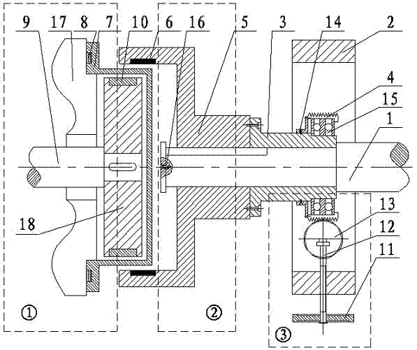
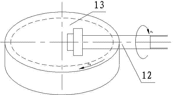
[0027] The working principle of embodiment 1: as figure 1 As shown, when the cylindrical outer rotor 5 rotates with the motor, the permanent magnet 6 arranged on its inner surface will form a rotating magnetic field in the air gap. According to the principle of electromagnetic induction, in the cylindrical inner rotor 18 An induced current is generated on the surface of the copper strip 10, and the current interacts with the rotating magnetic field to cause the inner rotor 18 to receive an electromagnetic torque in the same direction as the rotating magnetic field, thereby causing the inner rotor 18 to rotate; during the rotation of the outer rotor 5, At this time, when the hand wheel 11 is rotated, the friction wheel driving wheel 12 will move while rotating, which will cause the friction wheel driven wheel 13 to generate rotational motion, and the movement mode between the friction driven wheel 13 and the sleeve II4 is gear teeth. At this time, the sleeve II4, sleeve I3, and...
Embodiment 2
[0028] Embodiment 2: on the basis of embodiment 1, as figure 2 As shown, the transmission mechanism consisting of the inner rotor assembly ① and the outer rotor assembly ② consists of a conical outer rotor 5 containing a permanent magnet 6, a conical spacer sleeve 7 fixed on the base 17, and a conductor embedded in it. The cone-shaped inner rotor 18 is formed, and its purpose is to simultaneously change the facing area and the size of the air gap between the permanent magnet 6 and the conductor, so as to control the output torque better and faster; in addition, the radial direction of the coupling is reduced. Dimensions to meet some occasions where space is limited.
Embodiment 3
[0029] Embodiment 3: as Figure 5 As shown, the speed regulating device is similar to that in Embodiment 1. The transmission mechanism consists of a cylindrical outer rotor 5 containing a permanent magnet 6, a cylindrical spacer 7 fixed to the base 17, and a cylindrical inner rotor. 18, the structure of the inner rotor 18 includes inner rotor inner layer 19 and inner rotor outer layer 20, the inner rotor inner layer 19 is a solid rotor, the material is steel or cast iron, and the outer surface is plated with 2-5 mm thick Copper is the outer layer 20 of the inner rotor, thus forming a double cylinder structure. The working principle of this structure is the same as that of the solid rotor type, but it has the advantages of high transmission performance, good starting characteristics, and convenient processing.
PUM
 Abstract
Description
Claims
Application Information
 - R&D
- Intellectual Property
- Life Sciences
- Materials
- Tech Scout
- Unparalleled Data Quality
- Higher Quality Content
- 60% Fewer Hallucinations
Browse by: Latest US Patents, China's latest patents, Technical Efficacy Thesaurus, Application Domain, Technology Topic, Popular Technical Reports.
© 2025 PatSnap. All rights reserved.Legal|Privacy policy|Modern Slavery Act Transparency Statement|Sitemap|About US| Contact US: help@patsnap.com


