
Remote intelligent speed control axial asynchronous magnetic coupling and speed regulating method

A remote intelligent control, magnetic coupling technology, applied in control systems, control electromechanical transmission devices, energy industry and other directions, can solve the problems of difficult to accurately guarantee accuracy, low transmission efficiency, cumbersome operation, etc., to achieve stable speed and output torque Effect

Inactive Publication Date: 2012-08-22
JIANGSU UNIV
View PDF5 Cites 23 Cited by
  • Summary
  • Abstract
  • Description
  • Claims
  • Application Information

AI Technical Summary

Problems solved by technology

[0002] Magnetic drive technology is a new technology that uses the magnetic force generated by permanent magnet materials to realize the non-contact transmission of force or torque. The device that realizes this technology becomes a magnetic drive, and the magnetic coupling is one of them; The coupling uses the principle of magnetic induction to realize the combination and separation of the main and driven shafts of the machine through the magnetic force of the permanent magnet. There is no mechanical contact between the two, which overcomes the fatal defect of machine parts wear, eliminates vibration, and improves the transmission. efficiency, and can adjust the torque and transmission ratio in the process of power transmission arbitrarily, so that the magnetic coupling is widely used in petrochemical, mining, metallurgy, medicine and health, transportation and other fields; some axial asynchronous magnetic couplings are currently The motor uses a manual speed regulating device to adjust the meshing area between the conductor rotor and the permanent magnet to achieve output of different torques, thereby realizing adjustable speed, but the manual adjustment method is cumbersome to operate, and the accuracy is difficult to ensure accurately, so it is not suitable for Application in occasions with high precision requirements; how to accurately adjust the output torque in the magnetic coupling through the remote intelligent control system has become a new topic in the research direction of magnetic technology
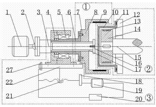
[0003] At present, a small number of patents have been researched on this kind of magnetic coupling. In the patent with the related application number CN200910232125.6, a permanent magnetic coupling composed of a cylindrical conductor rotor, a cylindrical permanent magnet rotor, and a regulator is disclosed. Magnetic speed governor, in which the cylindrical conductor rotor is installed on the input shaft, and the cylindrical permanent magnet rotor is installed on the outer ring part of the cylindrical permanent magnet rotor. Although this kind of magnetic coupling can realize the non-contact transmission of torque, but The shape and features of the adjuster are rarely mentioned in the patent; and an adjustable axial asynchronous magnetic coupling is disclosed in the patent application number CN201110219054.3, including: inner rotor assembly ①, outer rotor assembly ② The speed regulating device ③ mainly changes the meshing area between the permanent magnet and the copper bar through the movement transmission between the friction wheel and the driving wheel, and changes the output torque accordingly. The principle of this kind of magnetic coupling speed regulation is simple , convenient, but due to the slippage in the friction wheel movement, the rotation accuracy of the driven wheel is affected, and the transmission efficiency is low; the invention proposes a remote intelligent control adjustable speed axial asynchronous magnetic coupling, which is driven by a remote intelligent controller Controlling the rotation of the motor can well adjust the meshing area between the permanent magnets on the outer rotor and the guide bars on the inner rotor, thereby changing the output torque and realizing precise speed change, so it is obviously different from the above patents

Method used


Image

  • Remote intelligent speed control axial asynchronous magnetic coupling and speed regulating method
  • Remote intelligent speed control axial asynchronous magnetic coupling and speed regulating method
  • Remote intelligent speed control axial asynchronous magnetic coupling and speed regulating method

Examples


Embodiment 1

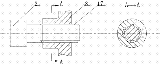
[0030] The working principle of embodiment 1: as figure 1 As shown, when the drive shaft controls the motor 1 and drives the outer rotor 8 to rotate, the permanent magnet 9 arranged on the inner surface of the outer rotor 8 will form a rotating magnetic field in the air gap. According to the principle of electromagnetic induction, the guide bars in the inner rotor 14 13, an induced current will be formed on the surface, and the induced current will induce an induced magnetic field and interact with the magnetic field of the permanent magnet, so that the inner rotor 14 rotates with the outer rotor 8; during the rotation of the outer rotor 8, the remote intelligent controller 20 A command is issued to drive and control the rotation of the motor 19. After being decelerated by the reduction mechanism 18, the rotation motion is converted into a feed motion through the ball screw 21, which drives the worktable 22, the bearing 5, the sleeve 6, and the outer rotor 8 to move left and ri...

Embodiment 2

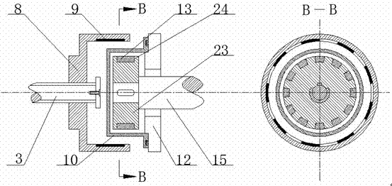
[0031] Embodiment 2: as image 3 As shown, similar to Embodiment 1, the inner rotor assembly ② is composed of the spacer 10 fixed on the base 12, the driven shaft 15, the inner rotor base 23, the guide bar 13 and the end ring 24, the inner rotor base The seat 23 is installed on the driven shaft 15, and the outer surface of the inner rotor base 23 is evenly distributed with deep groove structures along the circumferential direction. Guide bars 13 are placed in the grooves, and end rings 24 are fixed on both sides of the guide bars 13, so that The bars 13 form a closed loop. Since this structure does not require permanent magnet materials on the inner rotor, it is suitable for working under high temperature conditions.

Embodiment 3

[0032] Embodiment 3: as Figure 4 As shown, similar to Embodiment 1, the inner rotor assembly ② is composed of the spacer sleeve 10 fixed on the base 12, the driven shaft 15, the inner rotor inner layer 25, and the inner rotor outer layer 26. The inner rotor inner layer is 25 is a solid rotor, the material is steel or cast iron, and a layer of copper is plated on its outer surface, which is the outer layer 26 of the inner rotor, forming a double-layer cylindrical structure. The structure has the advantages of high transmission performance and good starting performance.


PUM


Abstract

The invention relates to a magnetic coupling, in particular to a remote intelligent speed control axial asynchronous magnetic coupling and a speed regulating method. The meshing area between a permanent magnet and a conductor can be well adjusted by taking a remote intelligent controller to drive and control a motor to rotate, and in such way, the volume of the output torque is changed and precise speed change is realized. According to the invention, the application range of the magnetic coupling is expanded. The remote intelligent speed control axial asynchronous magnetic coupling is suitable for working under the situations with violent vibration, dust and impurities and other harsh conditions. The remote intelligent speed control axial asynchronous magnetic coupling can be widely used in the petrochemical industry, metallurgical industry, mining industry and the like.

Description

technical field [0001] The invention relates to a magnetic coupling, in particular to a remote intelligent control adjustable speed axial asynchronous magnetic coupling and a speed regulating method, which are suitable for working under some severe vibrations, dust and other harsh conditions. Can be widely used in petrochemical, metallurgy, mining and other industries. Background technique [0002] Magnetic drive technology is a new technology that uses the magnetic force generated by permanent magnet materials to realize the non-contact transmission of force or torque. The device that realizes this technology becomes a magnetic drive, and the magnetic coupling is one of them; The coupling uses the principle of magnetic induction to realize the combination and separation of the main and driven shafts of the machine through the magnetic force of the permanent magnet. There is no mechanical contact between the two, which overcomes the fatal defect of machine parts wear, elimin...

Claims


Application Information

Patent Timeline
IPC IPC(8): H02K16/02H02P17/00
CPCY02P80/10
Inventor 杨超君李文双蒋毅一冯爱新周建忠
Owner JIANGSU UNIV
Learn More