Bogie for guide rail system vehicle
A technology of bogie and guide rail type, which is applied in the direction of steering control, steering mechanism, vehicle components, etc. It can solve the problems of rubber tire driving influence and rubber tire running instability, etc., to prolong life, improve driving stability and easy maintenance Effect
- Summary
- Abstract
- Description
- Claims
- Application Information
AI Technical Summary
Problems solved by technology
Method used
Image
Examples
Embodiment approach 1
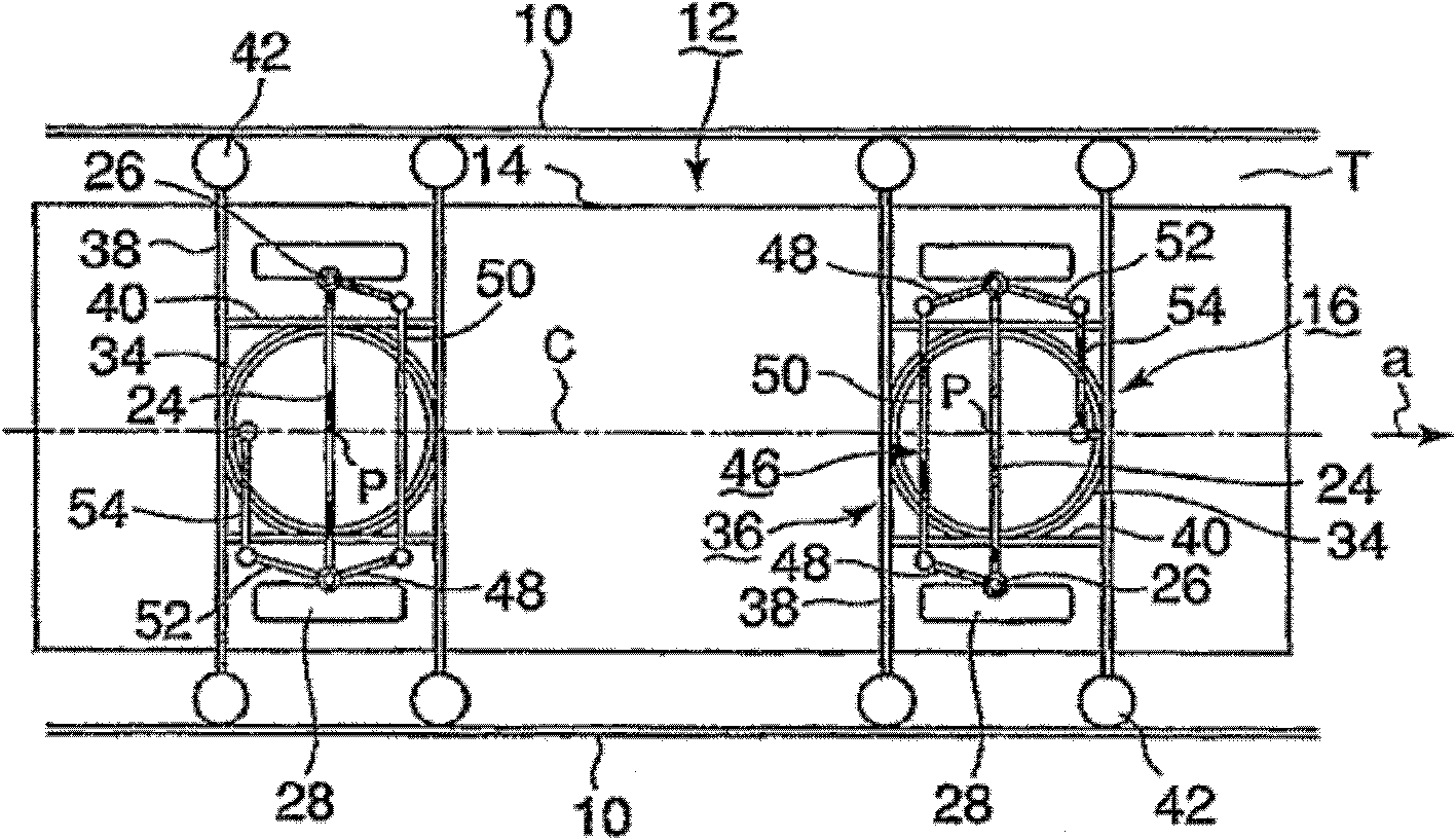
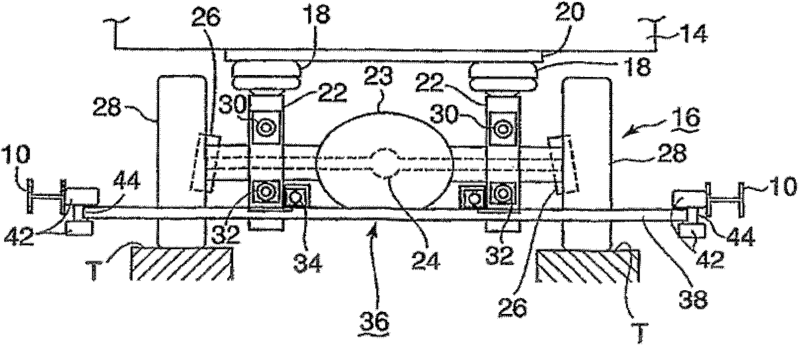
[0064] based on figure 1 and figure 2 A guide rail vehicle using the bogie according to the first embodiment of the present invention will be described. Such as figure 1 As shown, in the new traffic system, guide rails 10 are arranged along the track T on both sides of the track T of the traveling vehicle 12 . Two bogies 16 are equipped at the front and rear of each bogie vehicle. The bogie 16 is provided with a guide wheel 42 that is in contact with the rolling surface of the guide rail 10 and rolls, and the vehicle 12 travels on the track T under the guidance of the guide wheel 42 . figure 1 In , arrow a indicates the traveling direction of the vehicle 12 .
[0065] Alternatively, a guide rail may be provided at the center of the track T, and the guide wheels may roll in contact with both side surfaces of the track so as to sandwich the guide rail.
[0066] exist figure 2 In this case, a bogie 16 is attached to the lower surface of the vehicle body 14 via an air s...
Embodiment approach 2
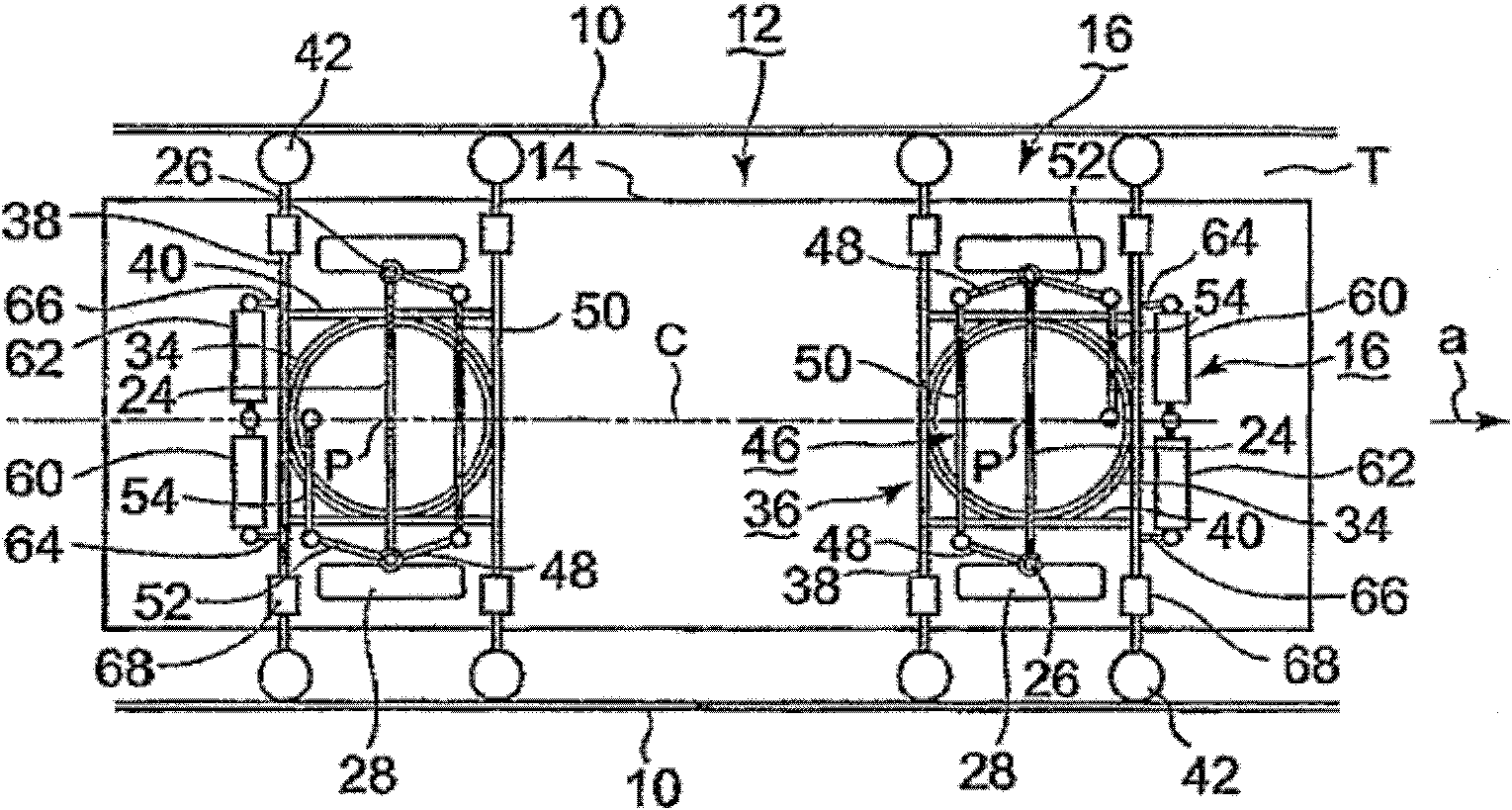
[0087] based on image 3 A second embodiment of the present invention will be described. exist image 3 Among them, this embodiment is the same as the first embodiment except for the structure described below. That is, with respect to the rotation of the guide frame 36, a return rod 60 that provides a restoring force in the forward direction and a rotation damper 62 that suppresses violent rotation are attached to the beam rod 38 on the vehicle end side of the guide frame 36 via the connecting rods 64 and 66, and It is arranged side by side with the beam rod 38 .
[0088] The restoring rod 60 is a structure connected to a buffer mechanism composed of a spring element and a damping element, and provides force to the guide wheel 36 in a direction returning to a neutral posture, which puts the rubber tire 28 in a forward state (for example, refer to Japanese Patent Laying-Open No. 2 -210150 Bulletin). The rotation damper 62 is constituted by, for example, a conventionally kno...
Embodiment approach 3
[0094] based on Figure 4 A third embodiment of the present invention will be described. In the present embodiment, a manipulation mechanism 46 having a different structure than that of the first embodiment is employed. That is, the tie rod 50 of the steering mechanism 46 (similar to the first embodiment, it is disposed closer to the center side in the front-rear direction of the vehicle body than the drive shaft 24) is composed of split rods 86a and 86b divided into two parts at the center position in the axial direction. The rods 86a and 86b are rotatably connected to each other, and the connecting point is connected to a receiving portion 88 protruding from the beam rod 38 provided on the center side in the front-rear direction of the vehicle body.
[0095] Therefore, the rotational motion of the guide frame 36 is directly transmitted to the steering pins 26 of the left and right rubber tires 28 via the receiving portion 88 and the split levers 86a, 86b, whereby the rubber ...
PUM
 Abstract
Description
Claims
Application Information
 - R&D
- Intellectual Property
- Life Sciences
- Materials
- Tech Scout
- Unparalleled Data Quality
- Higher Quality Content
- 60% Fewer Hallucinations
Browse by: Latest US Patents, China's latest patents, Technical Efficacy Thesaurus, Application Domain, Technology Topic, Popular Technical Reports.
© 2025 PatSnap. All rights reserved.Legal|Privacy policy|Modern Slavery Act Transparency Statement|Sitemap|About US| Contact US: help@patsnap.com


