
Boat drive comprising auxiliary drives

A technology of driving equipment and driving device, which is applied in the direction of mechanical gear transmission, ship propulsion, mechanical equipment, etc. It can solve the problems of angular deflection, large modification costs, and the inapplicability of transmission parts to pivotable ship driving equipment, etc., to achieve The effect of maintenance and assembly simplification

Active Publication Date: 2012-01-18
ZF FRIEDRICHSHAFEN AG
View PDF12 Cites 0 Cited by
  • Summary
  • Abstract
  • Description
  • Claims
  • Application Information

AI Technical Summary

Problems solved by technology

If the ship's drive system is to be retrofitted for dual-motor operation, this would require a considerable modification effort
Furthermore, the transmission described is not suitable for pivotable ship drives, since the angular deflection of the power-conducting shaft that is required for the rudder and oar is not solved

Method used


Image

  • Boat drive comprising auxiliary drives
  • Boat drive comprising auxiliary drives
  • Boat drive comprising auxiliary drives

Examples


Embodiment Construction

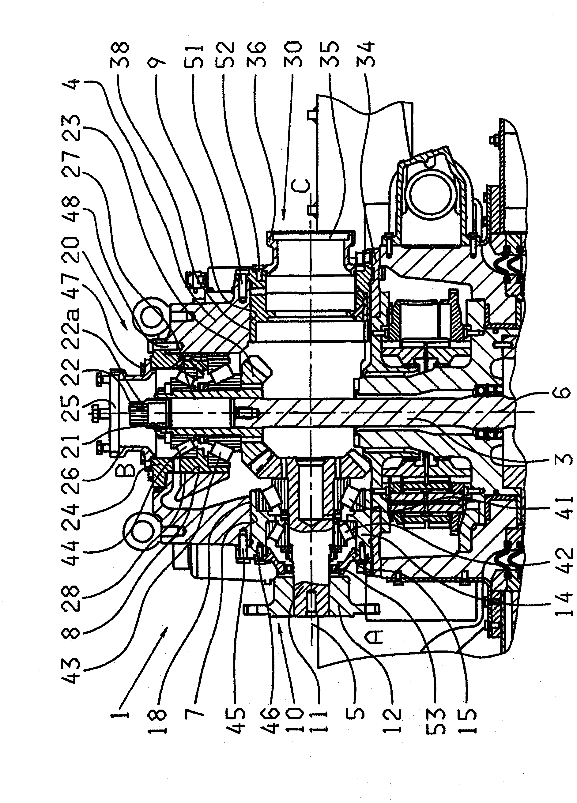
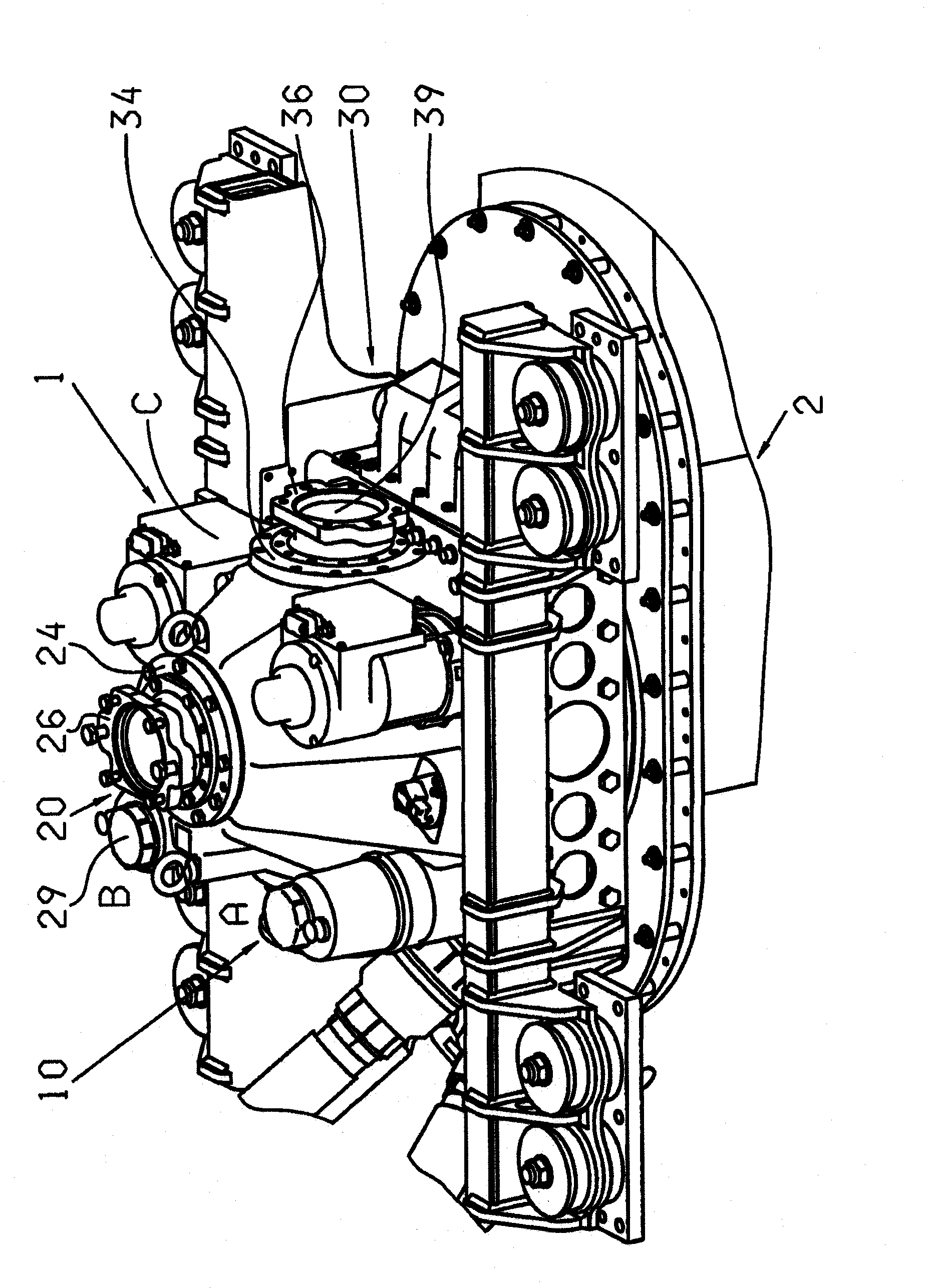
[0023] exist figure 1 A sectional view of the transmission unit 1 is shown in . The sectioning is carried out in a plane spanned by the axis of rotation 5 of the input shaft 11 and the axis of rotation 6 of the output shaft 3 , wherein the axis of rotation 5 lies in the longitudinal direction of the hull and is parallel to the axis of rotation 6 at right angles, and wherein the axis of rotation 6 intersects the axis of rotation 5 perpendicularly. The transmission unit 1 is arranged inside the hull. In the transmission housing 4 of the transmission unit 1, cylindrical inner contours 7, 8 and 9 are respectively formed at the three connecting points A, B and C, wherein the positions of the inner contours 7 and 9 are in relation to the axis of rotation 5 and the position of the inner contour 8 is coaxial with the axis of rotation 6 .

[0024] In the inner contour 7 , at the connection point A, a drive 10 is arranged coaxially to the axis of rotation 5 . In connection point A, ...


PUM


Abstract

The invention relates to a pivotable boat drive, comprising a transmission unit (1). The transmission unit (1) comprises, at a connection point (A), an input shaft (11) of a drive device (10), that can be driven by a drive motor and is arranged in such a way that it can be rotated about a first rotational axis (5), and an output shaft (3) that is coupled to the input shaft (11) and arranged in such a way that it can be rotated about a second rotational axis (8). The rotational axes (5, 6) are neither parallel nor concentric to each other. The transmission unit (1) has at least one other connection point (B, C) on which another drive device (20) that can be driven by another drive motor is provided for driving the output shaft (3).

Description

technical field [0001] The invention relates to a ship drive system for controlling and driving a ship according to the preamble of claim 1 . Background technique [0002] So-called pod drives are known, which are also referred to as pivotable ship drives or rudder paddles. Such a ship drive system for simultaneously controlling and driving a ship has a transmission unit inside the ship's hull and a control unit in the water below the ship's hull. At least one propeller is rotatably arranged on the control unit and is driven by a propeller shaft which is rotatably mounted inside the control housing. The control unit is pivotable about its vertical axis, which is substantially parallel to the vertical axis of the vessel, in order to control the vessel. The transmission element unit is coupled with the drive motor through a drive shaft. The drive motor is arranged inside the hull like the transmission unit. A crank gear is arranged in the transmission unit so that the driv...

Claims


Application Information

Patent Timeline
Patent Type & Authority Applications(China)
IPC IPC(8): B63H5/125B63H23/10
CPCB63H23/10B63H2005/1254B63H5/125Y10T74/19051Y10T74/1966Y10T74/1906
Inventor 费尔南多·加拉托丹莱莱·萨基阿多内·贝尔托洛
Owner ZF FRIEDRICHSHAFEN AG
Learn More