Control device of an air conditioning device of a motor vehicle and method for activating an air conditioning device with a fan

A technology for control devices and air-conditioning equipment, applied in the directions of air handling equipment, heating/cooling equipment, vehicle components, etc., to achieve the effect of reducing construction costs

Inactive Publication Date: 2007-04-18
SIEMENS AG
View PDF2 Cites 0 Cited by
  • Summary
  • Abstract
  • Description
  • Claims
  • Application Information

AI Technical Summary

Problems solved by technology

However, this requires complex devices to control the airflow of some

Method used


Image

  • Control device of an air conditioning device of a motor vehicle and method for activating an air conditioning device with a fan
  • Control device of an air conditioning device of a motor vehicle and method for activating an air conditioning device with a fan

Examples


Embodiment Construction

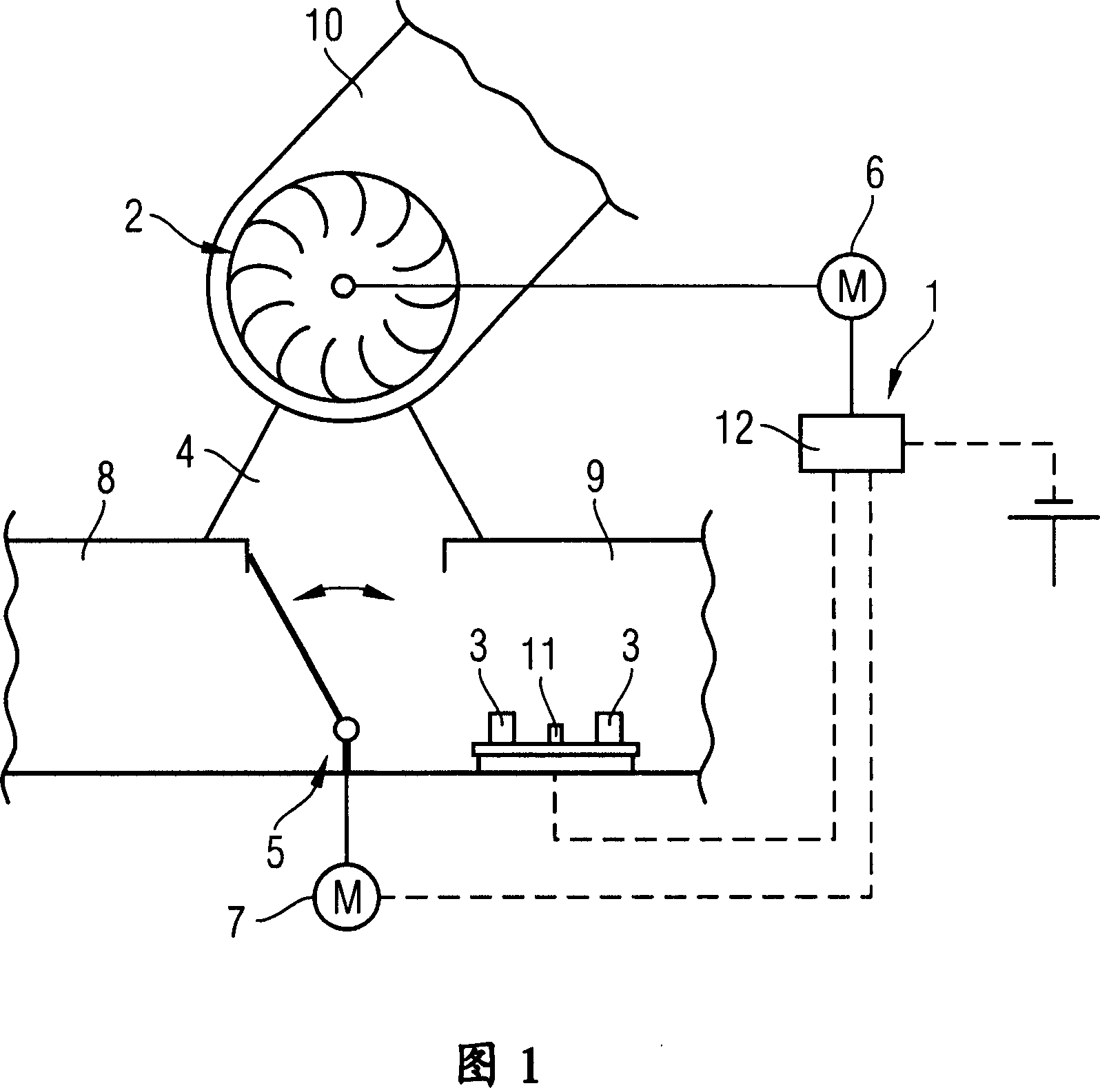
[0017] FIG. 1 schematically shows a control unit 1 of a motor vehicle with a fan 2 and heat-generating electronic components 3 arranged in the dashboard. The electronic components 3 are arranged in the intake connection 4 of the fan 2 directly behind the fresh-air recirculation baffle 5 . The fan 2 and the fresh air-circulating air baffle 5 can be driven by electric motors 6, 7, respectively. The intake connection 4 of the fan 2 can be selectively connected to the fresh air connection 8 or the recirculation air connection 9 via the fresh air-recirculation air baffle 5 . Air can be drawn in from the outside of the motor vehicle via the fresh air connection 8 , while air can be drawn in from the inside of the motor vehicle through the recirculation air connection 9 . Irrespective of the position of the fresh air-circulating air damper 5 , the fan 2 conveys the sucked-in air via the ventilation duct 10 to ventilation slots (not shown) in the motor vehicle interior. The motors 6...


PUM


Abstract

A control device of an air conditioning device of a motor vehicle has a fan, a control unit for activating the fan, and a suction connection of the fan arranged in the vicinity of electronic components generating heat. The electronic components are arranged upstream, relative to the flow of air toward the fan, of the suction connection of the fan. When the fan is switched on, the air surrounding the electronic components is extracted and therefore the heat generated by the electronic components is dissipated. An electric motor of the fan is activated by the control unit as a function of the heat generation of the electronic components.

Description

technical field [0001] The invention relates to a control device for an air-conditioning system of a motor vehicle, which has a controller for activating a fan. Furthermore, the invention relates to a method for activating an air conditioning system with a fan of a motor vehicle on the basis of the temperature of an electronic component to be cooled. Background technique [0002] A control device of this type is known, for example, from DE 41 36 207 C1. In this device, an electronic unit provided in a side recess separated from a cab of a motor vehicle is supplied with air through a heat exchanger of a heating and cooling device. This air then exits the side grooves and enters the cab. However, this design requires a complex air conduction arrangement. In addition, electronic units arranged in the ventilation area of ​​the air flow generated by the heating and cooling equipment can only be cooled insufficiently. [0003] Furthermore, DE 198 04 698 A1 discloses a motor ve...

Claims


Application Information

Patent Timeline
Patent Type & Authority Applications(China)
IPC IPC(8): B60H1/00
CPCB60H1/00849B60H1/00521B60H2001/00614
Inventor 托马斯·黑克
Owner SIEMENS AG
Why Eureka
Try Eureka