
Device and method for measuring axial force of working roll of slab strip hot rolling mill

A measuring device and work roll technology, which is applied in the direction of length measuring device, metal rolling, manufacturing tools, etc., can solve the problems of shutdown, lock door screw breaking, etc., and achieve the effect of convenient assembly and disassembly and direct measurement

Active Publication Date: 2012-01-25
北京中冶设备研究设计总院有限公司
View PDF4 Cites 11 Cited by
  • Summary
  • Abstract
  • Description
  • Claims
  • Application Information

AI Technical Summary

Problems solved by technology

[0002] The axial force of the work rolls of the strip mill is generated due to the axis crossing between the rolls during the rolling process. Research and experiments have shown that the axial force of the work rolls of most rolling mills is directed to the operating side, even if there is a bidirectional axial force, it will point to The axial force on the operating side is generally much greater than the axial force directed to the transmission side. The axial force of the work roll is an important factor affecting the life of the work roll bearing; It is realized by locking the door plate on the operating side. At present, the axial force of the work roll of this type of rolling mill is determined by experience. Generally, it is 3% to 5% of the rolling force. However, in actual use, the bolts of the door lock plate often break. A shutdown accident affects production. The cause of the accident is that the actual axial force is greater than the design value. Therefore, it is very necessary to directly detect the axial force acting on the work roll

Method used


Image

  • Device and method for measuring axial force of working roll of slab strip hot rolling mill
  • Device and method for measuring axial force of working roll of slab strip hot rolling mill
  • Device and method for measuring axial force of working roll of slab strip hot rolling mill

Examples


Embodiment Construction

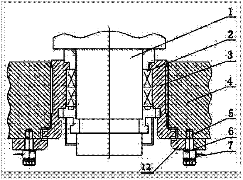
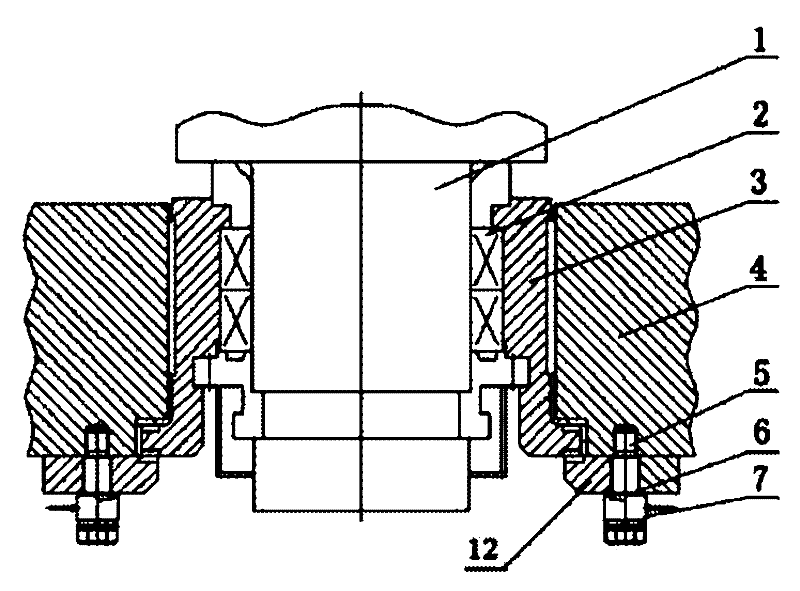
[0009] Below in conjunction with accompanying drawing, the measuring device and the method of the working roll axial force of the strip hot rolling mill of the embodiment of the present invention are described in further detail: as figure 1 Shown: Provide a measuring device for the axial force of the work roll of the strip hot rolling mill, mainly including the work roll 1, the bearing 2, the bearing seat 3, the rolling mill frame 4, and the door lock plate 12, and the feature is: the design has an extended lock door plate Screw 5, by lengthening the lock door plate screw 5, the rolling mill frame 4 and the lock door plate 12 are fixedly connected together, and a force sensor 7 is set on the inner side of the lengthened lock door plate screw 5 nut and the outside of the lock door plate 12, and the lengthened lock door plate Between the door lock plate 12 of suit on the screw 5 and the load cell 7, there is an equal load pad 6 for improving the stress of the sensor; on each side...


PUM


Abstract

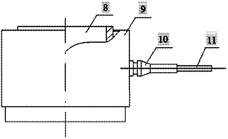
The invention provides a device for measuring the axial force of a working roll of a slab strip hot rolling mill. The device comprises the working roll, a bearing, a bearing block, a rolling mill frame and a door locking plate, and is characterized by being provided with a lengthened door locking plate screw; a force measuring sensor is sleeved on the inner side of a lengthened door locking platescrew nut and the outer side of the door locking plate; a load balancing pad is sleeved between the door locking plate sleeved on the lengthened door locking plate screw and the force measuring sensor; and the force measuring sensor consists of an annular elastic body, a waterproof shell, a waterproof joint and a cable. The invention also provides a method for measuring the axial force of the working roll of the slab strip hot rolling mill. The method comprises the following steps of: disassembling a screw of the original door locking plate on the operating side of the rolling mill, arrangingthe lengthened door locking plate screw, the force measuring sensor and the load balancing pad at corresponding positions, and assessing a signal into a strain gauge to measure the axial force of theoperating side directed by the working roll. The device and the method have the advantages that the device is convenient to assemble and disassemble, the axial force of the operating side directed bythe working roll can be measured directly, and the measuring accuracy is 3 percent.

Description

Technical field: [0001] The invention relates to the technical field of measuring the axial force of work rolls in rolling mills, in particular to a measuring device and method suitable for the axial force of work rolls in a strip hot rolling mill with a door lock plate structure. Background technique: [0002] The axial force of the work rolls of the strip mill is generated due to the axis crossing between the rolls during the rolling process. Research and experiments have shown that the axial force of the work rolls of most rolling mills is directed to the operating side, even if there is a bidirectional axial force, it will point to The axial force on the operating side is generally much greater than the axial force directed to the transmission side. The axial force of the work roll is an important factor affecting the life of the work roll bearing; It is realized by locking the door plate on the operating side. At present, the axial force of the work roll of this type of...

Claims


Application Information

Patent Timeline
IPC IPC(8): B21B38/08
Inventor 闫瑾唐志惠吴亚谊
Owner 北京中冶设备研究设计总院有限公司
Learn More