Bending-compression mould for processing fastener

A buckle and mold technology, applied in the field of bending and pressing molds, can solve problems such as unsatisfactory benefits, large production space investment, increase of defective products, etc., to improve assembly consistency and assembly quality, simplify assembly procedures, and have a compact and ingenious structure. Effect

Active Publication Date: 2012-01-25
SHANGHAI AISHIDA ROBOT CO LTD
View PDF5 Cites 7 Cited by
  • Summary
  • Abstract
  • Description
  • Claims
  • Application Information

AI Technical Summary

Problems solved by technology

[0005] 1. Large manpower input;
[0006] 2. The investment in mold equipment and production space is relatively large;
[0007] 3. Low production efficiency and unsatisfactory benefits;
[0008] 4. Since multi-process assembly needs to carry semi-finished products between station

Method used


Image

  • Bending-compression mould for processing fastener
  • Bending-compression mould for processing fastener
  • Bending-compression mould for processing fastener

Examples


Embodiment Construction

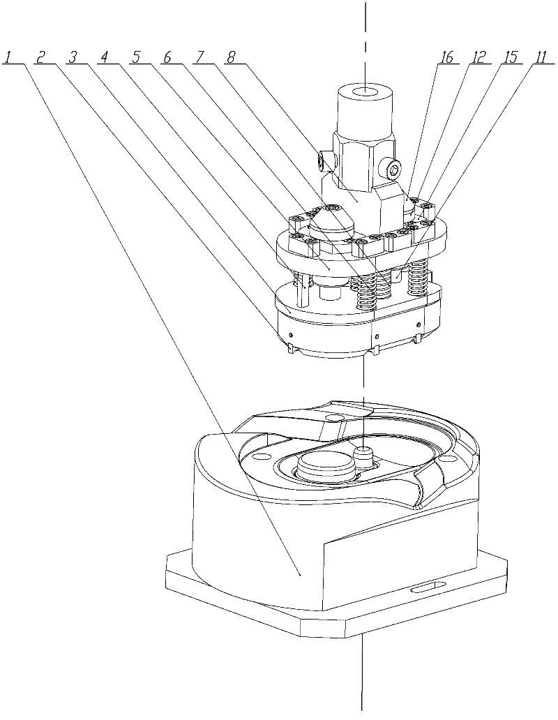
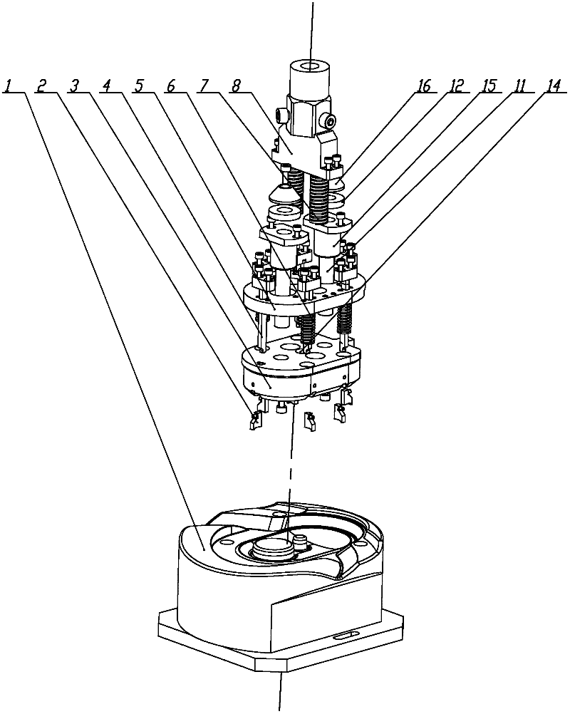
[0035] As shown in the bending die, the top of the lower punch 3 is provided with an upper push plate 5 and a connecting block 8, the bottom of the connecting block 8 is fixedly installed on the upper surface of the upper push plate 5, and the lower punch 3 and the upper push plate 5 They are connected by two guide columns 11 that pass through the upper push plate. The bottom of each guide post 11 is fixedly connected to the lower die 3 , the top is provided with a limit block 16 , and each guide post 11 is covered with a guide sleeve 15 fixed on the upper push plate 5 . Five booster springs 6 and two symmetrically arranged preload springs 7 are arranged between the upper push plate 5 and the lower die 3 .

[0036] The bottom of the lower die 3 is fixed with 6 horizontal bending knives 2, and the upper push plate 5 is fixed with 6 longitudinal bending knives 4 penetrating the lower die, which consists of a horizontal bending knife and a longitudinal bending knife. Crimping kn...


PUM


Abstract

A traditional common mould used for carrying out bending-compression assembly between two parts comprises two moulds: a transversal bending mould and a longitudinal bending mould, which has a fussy and complicated assembly process and low production efficiency. The invention provides a bending-compression mould, which comprises a lower positioning concave die and a lower punching die matched withthe lower positioning concave die for use, and is characterized in that an upper push plate and a connecting block are arranged above the lower punching die; the bottom part of the connecting block is fixedly arranged on the upper surface of the upper push plate; the lower punching die and the upper push plate are connected through a plurality of guide posts penetrating through the upper push plate; the bottom part of each guide post is fixedly connected onto the lower punching die; the top part of the guide post is provided with a stop block; a plurality of booster springs and a plurality ofpre-stressing springs are arranged between the upper push plate and the lower punching die; a plurality of transversal bending tools are fixed at the bottom part of the lower punching die; a plurality of longitudinal bending tools penetrating the lower punching die are fixed on the upper push plate; and the tool bits of the longitudinal bending tools are arranged next to the side walls of the transversal bending tools. By adopting the bending-compression mould, the process is simplified, and the production efficiency is improved.

Description

technical field [0001] The invention relates to a mold for bending and pressing assembly of products, in particular to a bending and pressing mold for bending and pressing a buckle used for assembly between two parts and completing the assembly. Background technique [0002] At present, the commonly used mold used for bending and pressing assembly between two parts is composed of two molds: a transverse bending die and a longitudinal bending die. Usually, it is divided into the following assembly processes: ① place the two parts, ② press the two Components, ③Horizontal bending die performs horizontal semi-finished bending on the "┃" vertical plate, and bends it into a "━┓"-shaped folding plate, ④Remove the semi-finished product and transfer it to the next station, ⑤Place the two parts again components, ⑥press the two parts again, ⑦longitudinal bending die for longitudinal bending, and [0003] The "━┓"-shaped folding plate is processed into a "┏┓"-shaped buckle, and the two...

Claims


Application Information

Patent Timeline
IPC IPC(8): B21D37/10
Inventor 陈合林
Owner SHANGHAI AISHIDA ROBOT CO LTD
Why Eureka
Try Eureka