
Delivery table transmission method and electric delivery table

An electric and transmission structure technology, applied in medical science, surgery, operating tables, etc., can solve the problems of increasing the work intensity of medical staff, affecting the normal operation of childbirth operations, and the safety of babies cannot be guaranteed. It achieves a smart and compact structure, Strong integrity, fixed, reliable and stable effect

Inactive Publication Date: 2015-06-10
湖州市南浔鑫江医疗器械设备有限公司
View PDF4 Cites 2 Cited by
  • Summary
  • Abstract
  • Description
  • Claims
  • Application Information

AI Technical Summary

Problems solved by technology

Using this kind of delivery bed, the puerpera can give birth to the baby with the help of gravity, but these delivery beds are not equipped with a special delivery bed auxiliary table, and the delivery bed structure is a hard frame structure, and the safety of the baby cannot be guaranteed. It is easy to bruise the baby; and, because there is no protective pad, the midwife doctor is a little careless, and the baby is easy to fall to the ground after birth
Therefore, in order to protect babies more safely, there are also a small number of manual delivery bed auxiliary tables. In an emergency, it is extremely inconvenient to use and may affect the normal operation of the delivery operation
In addition, due to manual operation, the lifting speed is uneven and the operation is relatively unstable.

Method used


Image

  • Delivery table transmission method and electric delivery table
  • Delivery table transmission method and electric delivery table
  • Delivery table transmission method and electric delivery table

Examples


Embodiment Construction

[0021] The present invention will be further described below in conjunction with the accompanying drawings and embodiments, but not as a basis for limiting the present invention.

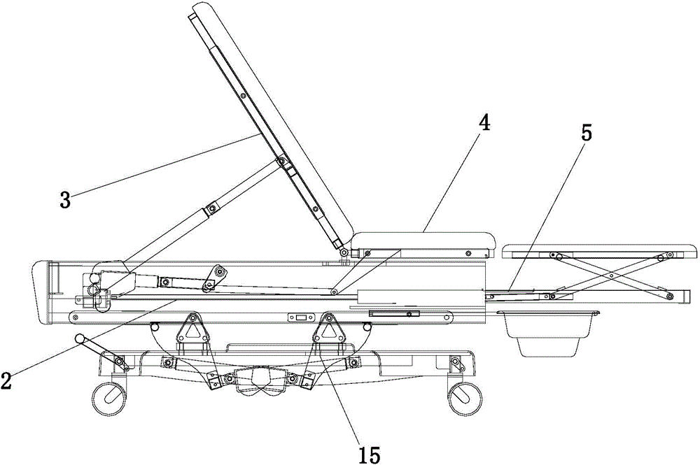
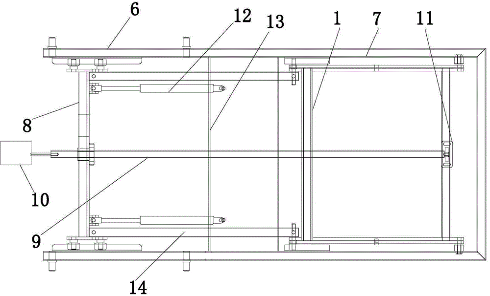
[0022] Example. A delivery bed transmission method, including the transmission method of the lifting table and the transmission method of the auxiliary table, characterized in that: the transmission method of the auxiliary table is that the motor drives the screw to rotate forward and the auxiliary table is in the middle through the elastic force of the air rod. The overall movement in the guide groove of the box, when it moves to the desired position, the outer frame of the auxiliary table stops moving, and the inner frame of the auxiliary table continues to move under the action of the screw, and then compresses the air rod, and the scissor fork lifting mechanism rises, In this way, the auxiliary table can be raised; the motor is reversed, and the scissor fork lifting mechanism is lowered under th...


PUM


Abstract

The invention discloses a delivery table transmission method and an electric delivery table. The delivery table transmission method includes transmission methods of a lifting table and an auxiliary table. The transmission method of the auxiliary table includes that a motor drives a screw to rotate clockwise, and the auxiliary table is enabled to integrally move in a guide groove of a middle tank by the aid of elasticity of air rods; when the auxiliary table moves to the required position, an outer frame of the auxiliary table stops moving, an inner frame of the auxiliary table keeps moving under the action of the screw, the air rods are compressed to allow a scissors fork lifting mechanism to rise and thus drive the auxiliary table to rise. The motor rotates anticlockwise, the scissors fork lifting mechanism descends under the action of stretching of the air rods and the anticlockwise rotation of the screw, the screw keeps rotating anticlockwise to pull the stretched air rods, and thus the auxiliary table moves back and stops at the required position. The delivery table comprises a base, a lifting table is arranged on the base and provided with an adjustable back plate and a cushion plate, and an auxiliary table transmission structure is arranged on the inner side of the lifting table. The delivery table can automatically operate and is convenient in use, simple in operation and stable to operate.

Description

technical field [0001] The invention relates to obstetric midwifery equipment, in particular to a delivery bed transmission method and an electric delivery bed. Background technique [0002] Most of the delivery beds used in the obstetrics and gynecology departments of domestic hospitals are supine position structures, and the puerpera will put both legs on the left and right supports higher than the breech position during delivery. Some hospitals adopt delivery beds with seat structure and adjustable backrest. Using this kind of delivery bed, the puerpera can give birth to the baby with the help of gravity, but these delivery beds are not equipped with a special delivery bed auxiliary table, and the delivery bed structure is a hard frame structure, and the safety of the baby cannot be guaranteed. It is easy to bruise the baby; and, because there is no protective pad, the midwife doctor is a little careless, and the baby is easy to fall to the ground after birth. Therefore...

Claims


Application Information

Patent Timeline
Patent Type & Authority Applications(China)
IPC IPC(8): A61G13/08
Inventor 朱建斌
Owner 湖州市南浔鑫江医疗器械设备有限公司
Learn More