Heat resistant article having thermal barrier coatinging

a technology of thermal barrier coating and heat resistance article, which is applied in the field of heat resistance articles with thermal barrier coating, can solve the problems of easy damage, limited heat resistance temperature, and peeling off of ceramic coating, and achieve the effect of long operation tim

Active Publication Date: 2005-06-23
MITSUBISHI HITACHIPOWER SYST LTD
View PDF10 Cites 31 Cited by
  • Summary
  • Abstract
  • Description
  • Claims
  • Application Information

AI Technical Summary

Benefits of technology

[0015] An object of the present invention is to provide heat resistant articles with a thermal barrier coating having heat resisting property, anti-corrosion and anti-oxidation properties for a long operation time.

Problems solved by technology

However, there is a limit to a heat resisting temperature.
However, since TBC that is subjected to a harsh heat load condition, there easily occurs damage such as peeling off of the ceramic coat from the substrate.
Particularly, in the gas turbines operated at high temperatures for increasing efficiency, heat load on the gas turbines is very harsh so that the ceramic coat tends to peel off more easily.
Since the ceramic layer is less toughness and less strength than the substrate and bond coating, generation and development of cracks or peeling off easily occur due to the linear thermal expansion difference between the subbstrate or bond coating and ceramic layer or by quick temperature change at the time of start and stop of the gas turbine.
As a result, cracks are formed in the ceramic coat.
However, in the gas turbines to which a very large thermal load is applied, the above method was not satisfactory.
If the maximum stress value exceeds the strength of the ceramic coat, new initial cracks generate in the ceramic coat, or development of new initial cracks starts from the defects such as cracks or voids in the ceramic coat.
Further, the cracks may progress or spread by repetition of compression-expansion stress.
This is because the porous coat would not produce a ceramic coat wherein cracks extend in the direction of the thickness of the continuous ceramic coat, even when thermal stress is applied to the ceramic coat.
However, it was impossible to prevent the generation of cracks extending in the lateral direction of the coat (along the surface of the coat) together with the cracks extending in the thickness direction.
The ceramic coat in the neighborhood of the boundary between the under coat or the bond coating and the coat where the maximum stress occurs, if the cracks extending in the thickness direction are present, they may develop by the repetition of stresses, which leads to peeling off of the ceramic coat.
Further, since the coat has cracks that extend through the thickness of the coat, oxidative and corrosive substances easily arrive at the bond coating through the cracks.
As having been discussed, the conventional thermal barrier coating was not sufficient in view points of heat resistance, long term anti-oxidation as heat resistant articles for gas turbines or airplane engines whose operation temperature is extremely high.

Method used


Image

  • Heat resistant article having thermal barrier coatinging
  • Heat resistant article having thermal barrier coatinging
  • Heat resistant article having thermal barrier coatinging

Examples


embodiment 1

(Embodiment 1)

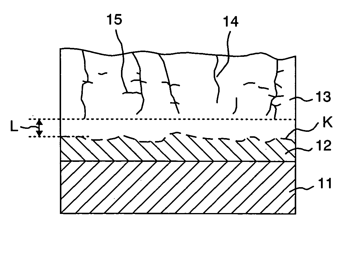
[0039] A Ni base super alloy (Rene′−80; Ni—14% Cr—4% Mo—3% Al—5% Ti—0.5% Co) of a disc form having a diameter of 25 mm and a thickness of 5 mm was used as a test piece. Powder of MCrAlY alloy (Co—32% Al—21% Cr—8% Al—0.5% Y) was applied to the surface of the test piece by a low pressure plasma spray method to form a metal bond coating.

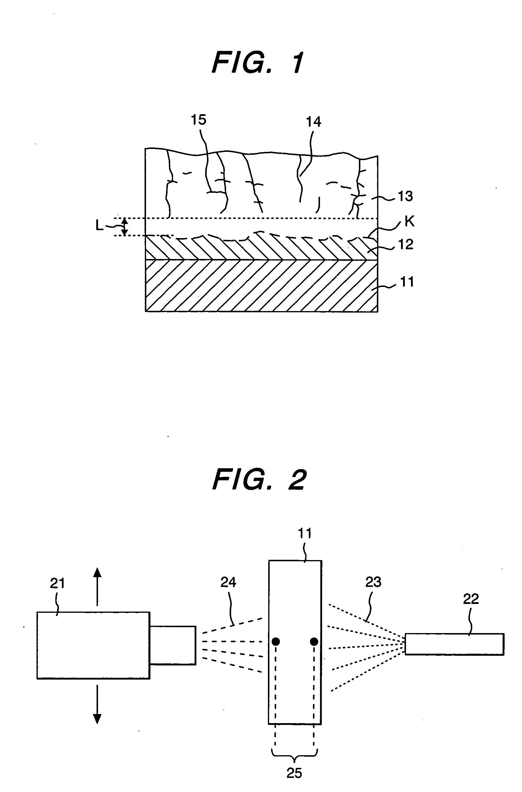
[0040] The thickness of the metal bond coating was about 100 μm. Then, a thermal barrier coating of the present invention having a thickness of about 500 μm was formed on the bond coating by an atmospheric plasma spray method. The spray conditions were: ceramic powder of ZrO2—8 weight % Y2O3 was introduced into a plasma jet using a mixed gas of N2—18% H2 (a plasma output: about 100 kW). The spray distance was 90 mm, and the traverse speed of a spray gun was 30 m / min. A thickness per one pass (a thickness of the barrier coat formed by one spray pass) was 50 μm. As shown in FIG. 2, compressed air was blown to the backside face of the test p...

embodiment 2

(Embodiment 2)

[0059] The present inventors prepared a ceramic coating gas turbine blade based on the test results using the fundamental test pieces of the embodiment 1. In the following, this will be explained.

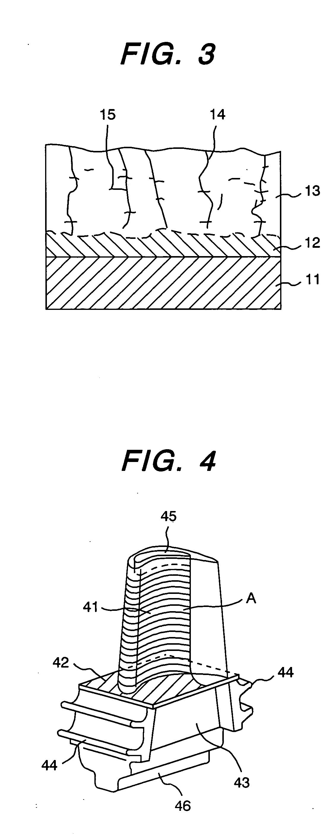
[0060] The perspective view of the gas turbine structure is shown in FIG. 4. In this drawing, the gas turbine blade is made of Ni base heat resisting super alloy (Rene′−80), which is used as the first stage blade, for example. The blade structure comprises the blade 41, a platform section 42, a shank portion 43, a seal fin 44 and a tip pocket 45. The structure is fitted by means of a dovetail 45 to a rotor disc. The blade has a blade length of 100 mm and a length from the platform to the end is 120 mm. The blade has a cooling hollow (not shown), which is formed from the dovetail 46 through the blade 41 to cool it with air or steam. Although the ceramic coated blade is most suitable for the first stage blade, it can be used for second stage blade and others. The thermal barrie...


PUM

PropertyMeasurementUnit
thicknessaaaaaaaaaa
porosityaaaaaaaaaa
thicknessaaaaaaaaaa

Abstract

A thermal barrier coating comprises a bond coating 12 made of high temperature corrosion resistance superior to a substrate 11 and a thermal barrier coating 13 made of ZrO2 series ceramics formed on the bond coating. The thermal barrier coating has cracks extending in the direction of the thickness of the barrier coat. Substantially all of the tips of the cracks have a distance between the tips and the boundary at the substrate side.

Description

CLAIM OF PRIORITY [0001] The present application claims from Japanese patent application Ser No. 2003-420281, filed on 18th of December, 2003, the content of which is hereby incorporated by reference into this application. DESCRIPTION OF THE INVENTION [0002] 1. Technical Field [0003] The present invention relates to a heat resistant article having a thermal barrier coating and a heat resistant article for gas turbines having the thermal barrier coating. [0004] 2. Related Art [0005] In recent years, an operating temperature of a gas turbine is becoming higher and higher for the purpose of increasing efficiency of operation-of the gas turbine. Therefore, durability of high temperature articles such as combustors, turbine blades and nozzles at high temperatures is strongly desired. Under such the background, development of heat resisting alloys having a high strength and high reliability at high temperatures is being progressed. However, there is a limit to a heat resisting temperature...

Claims


Application Information

Patent Timeline
Patent Type & Authority Applications(United States)
IPC IPC(8): F01D5/28B05D1/08B32B15/04C23C4/02C23C4/08C23C4/10C23C28/00F02C7/00H05H1/26
CPCC23C4/02C23C28/3215C23C28/3455Y02T50/67Y10T428/12861Y10T428/26Y10T428/12944Y10T428/12611Y10T428/263Y10T428/24997Y02T50/60
Inventor ARIKAWA, HIDEYUKIMEBATA, AKIRAKOJIMA, YOSHITAKAICHIKAWA, KUNIHIRO
Owner MITSUBISHI HITACHIPOWER SYST LTD
Why Eureka
Try Eureka