Plasma-generating device, plasma surgical device and use of plasma surgical device

a technology which is applied in the field of plasma surgical device and plasma generating device, can solve the problems of contaminating the gas plasma, affecting the surgical area, and affecting the surgical effect, so as to reduce the risk and facilitate the operation

Active Publication Date: 2007-01-25
PLASMA SURGICAL INVESTMENTS
View PDF98 Cites 32 Cited by
  • Summary
  • Abstract
  • Description
  • Claims
  • Application Information

AI Technical Summary

Benefits of technology

[0017] By using a plasma chamber, a possibility of forming a space around the cathode, especially the tip of the cathode closest to the anode, can advantageously be provided. Consequently, the plasma chamber allows the outer dimensions of the plasma-generating device to be relatively small. The space around the cathode tip is convenient to reduce the risk that the high temperature of the cathode in operation damages and / or degrades material of the device, which material adjoins the cathode. In particular this is important for devices intended for surgical applications where there is a risk that degraded material can contaminate the plasma and accompany the plasma into a surgical area, which may cause detrimental effects to a patient. A plasma chamber according to the invention is particularly advantageous with long continuous times of operation.
[0042] The plasma chamber is suitably formed by an intermediate electrode positioned closest to the cathode tip. By integrating the plasma chamber as part of an intermediate electrode, a simple construction is provided. Similarly, it is convenient that the plasma channel is formed at least partly by at least one intermediate electrode which is positioned at least partly between said cathode and said anode.

Problems solved by technology

When making plasma devices with small dimensions, there is often a risk that material adjacent to the cathode is heated to high temperatures due to the temperature of the cathode, which in some cases may exceed 3000° C. At these temperatures there is a risk that material adjacent to the cathode is degraded and contaminates the gas plasma.
Contaminated gas plasma may, for instance, introduce undesirable particles into the surgical area and may be injurious to a patient who is being treated.

Method used


Image

  • Plasma-generating device, plasma surgical device and use of plasma surgical device
  • Plasma-generating device, plasma surgical device and use of plasma surgical device

Examples


Embodiment Construction

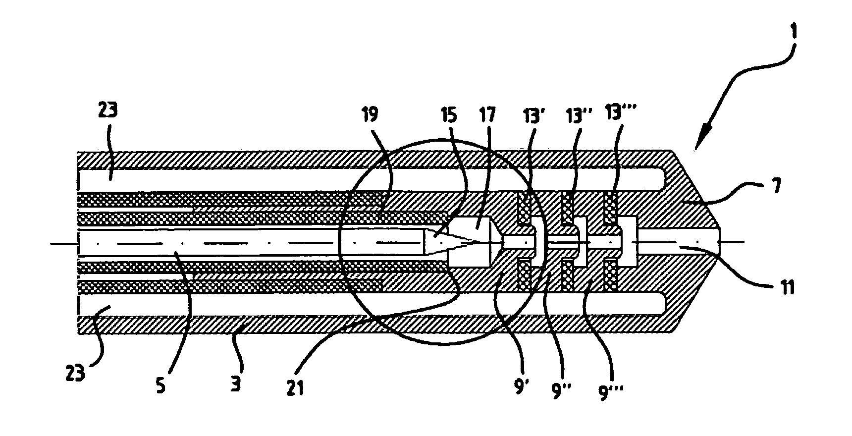
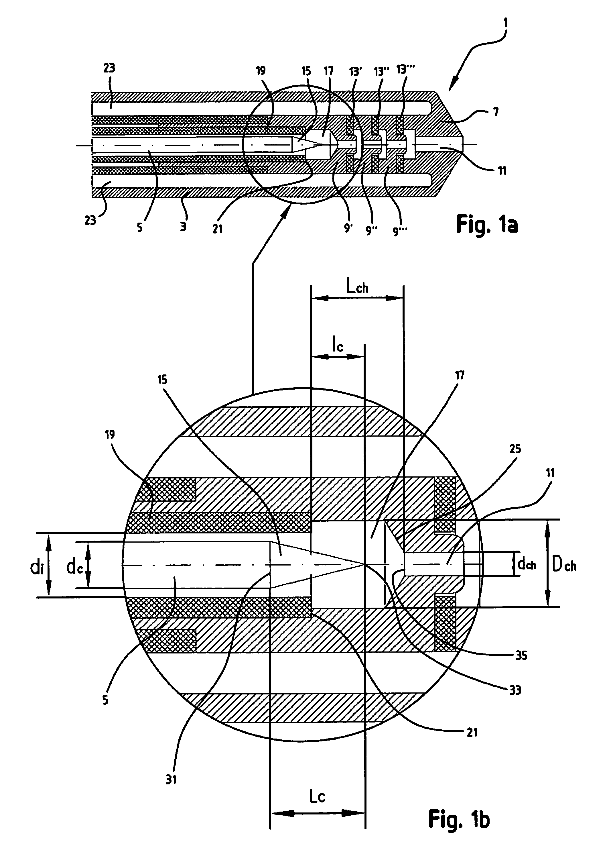
[0051]FIG. 1a shows in cross-section an embodiment of a plasma-generating device 1 according to the invention. The cross-section in FIG. 1a is taken through the centre of the plasma-generating device 1 in its longitudinal direction. The device comprises an elongate end sleeve 3 which accommodates a plasma-generating system for gene-rating plasma which is discharged at the end of the end sleeve 3. The generated plasma can be used, for instance, to stop bleeding in tissues, vaporise tissues, cut tissues etc.

[0052] The plasma-generating device 1 according to FIG. 1a comprises a cathode 5, an anode 7 and a number of electrodes 9′, 9″, 9′″ arranged between the anode and the cathode, in this text referred to as intermediate electrodes. The intermediate electrodes 9′, 9″, 9′″ are annular and form part of a plasma channel 11 which extends from a position in front of the cathode 5 and further towards and through the anode 7. The inlet end of the plasma channel 11 is positioned at the cathod...


PUM


Abstract

The present invention relates to a plasma-generating device, comprising an anode, a cathode and a plasma channel which in its longitudinal direction extends at least partly between said cathode and said anode. The end of the cathode which is directed to the anode has a cathode tip tapering towards the anode, a part of said cathode tip extending over a partial length of a plasma chamber connected to the plasma channel. The plasma chamber has a cross-sectional surface, transversely to the longitudinal direction of the plasma channel, which exceeds the cross-sectional surface, transversely to the longitudinal direction of the plasma channel, of an opening, positioned closest to the cathode, of the plasma channel. The invention also concerns a plasma surgical device and use of such a plasma surgical device.

Description

CLAIM OF PRIORITY [0001] This application claims priority of a Swedish Patent Application No. 0501604-3 filed on Jul. 8, 2005. FIELD OF THE INVENTION [0002] The present invention relates to a plasma-generating device, comprising an anode, a cathode and a plasma channel which in its longitudinal direction extends at least partly between said cathode and said anode. The invention also relates to a plasma surgical device and use of a plasma surgical device in the field of surgery. BACKGROUND ART [0003] Plasma devices relate to the devices which are arranged to generate a gas plasma. Such gas plasma can be used, for instance, in surgery for the purpose of causing destruction (dissection) and / or coagulation of biological tissues. [0004] As a rule, such plasma devices are formed with a long and narrow end or the like which can easily be applied to a desired area that is to be treated, such as bleeding tissue. At the tip of the device, a gas plasma is present, the high temperature of which...

Claims


Application Information

Patent Timeline
Patent Type & Authority Applications(United States)
IPC IPC(8): A61B18/14
CPCH05H1/34H05H2001/3484H05H2001/3452H05H1/3452H05H1/3484A61B18/042
Inventor SUSLOV, NIKOLAY
Owner PLASMA SURGICAL INVESTMENTS
Why Eureka
Try Eureka