Normally closed pneumatic pipe clamp

A technology of moving tubes and cylinders, which is applied in the field of automatic control of explosives and explosives, can solve problems such as safety hazards, difficulty in determining the state of valve opening and closing, and accidents, and achieves the effects of high adaptability, ensuring installation accuracy, and convenient installation

Active Publication Date: 2016-08-24
XIAN MODERN CHEM RES INST
View PDF7 Cites 3 Cited by
  • Summary
  • Abstract
  • Description
  • Claims
  • Application Information

AI Technical Summary

Problems solved by technology

Commonly used pinch valves have certain potential safety hazards when used for the transportation of energetic liquid materials because the casing is arranged inside the valve body, and it is difficult to visually observe the wear degree of the casing and whether there is leakage. When the pinch valve loses its driving force, it is difficult to determine the opening and closing state of the valve, which may lead to accidents

Method used


Image

  • Normally closed pneumatic pipe clamp
  • Normally closed pneumatic pipe clamp
  • Normally closed pneumatic pipe clamp

Examples


Embodiment 1

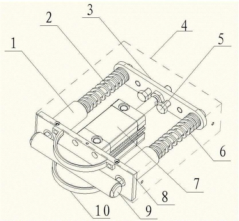
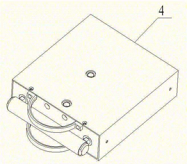
[0027] Such as figure 1 , figure 2 , a normally closed pneumatic pipe clamp is characterized in that it includes a sliding sleeve (1), a guide shaft (2), a connecting plate (3), a casing (4), an adjusting pin (5), a spring (6), a cylinder ( 7), cylinder mounting plate (8), pressure head (9), limit sleeve (10).

[0028] The cylinder 7 can be a FESTO AND series compact cylinder, which is installed on the cylinder mounting plate (8) through the side end flange without the extension rod, and the connecting plate (3) is fixed on the extension rod of the cylinder (7). One end of the guide shaft (2) is installed on the connecting plate (3), and is matched with the sliding sleeve (1) fixed on the cylinder mounting plate (8), and the pressure head (9) is connected to the other end of the guide shaft (2) Above, a gap for accommodating the hose is formed between the pressure head (9) and the cylinder mounting plate (8).

[0029] The spring (6) can be Misumi rectangular compression sp...

Embodiment 2

[0039] Such as figure 1 , figure 2 , a normally closed pneumatic pipe clamp is characterized in that it includes a sliding sleeve (1), a guide shaft (2), a connecting plate (3), a casing (4), an adjusting pin (5), a spring (6), a cylinder ( 7), cylinder mounting plate (8), pressure head (9), limit sleeve (10).

[0040] The cylinder (7) can be a FESTO AND series compact cylinder, which is installed on the cylinder mounting plate (8) through the side end flange without the extension rod, and the connecting plate (3) is fixed on the extension rod of the cylinder (7) One end of the guide shaft (2) is installed on the connecting plate (3), and is matched with the sliding sleeve (1) fixed on the cylinder mounting plate (8), and the pressure head (9) is connected to the end of the guide shaft (2). On the other end, a gap for accommodating the hose is formed between the head (9) and the cylinder mounting plate (8).

[0041] The spring (6) can be Misumi rectangular compression spri...


PUM


Abstract

In order to ensure the technological process safety, a switch valve for an energy-containing liquid material conveying pipeline reduces the force stimulating effect as much as possible during valve core action, and a pipe clamp valve is generally selected. For the common pipe clamp valve, a sleeve is arranged inside a valve body, and the conditions of sleeve abrasion degree and whether the leakage exists or not are difficult to be directly observed, so that certain potential safety hazard exists when energy-containing liquid materials are conveyed. For the existing pipe clamp valve, under the unexpected conditions such as driving force loss (such power supply or gas source cutting off), the valve opening state is difficult to determine, and the accident occurrence can be caused. The invention provides a normally closed pneumatic pipe clamp tightly locked by the spring force, and solves the problems. The normally closed pneumatic pipe clamp comprises slide sleeves (1), guide shafts (2), a connecting plate (3), a case (4), regulating pins (5), springs (6), an air cylinder (7), an air cylinder installing plate (8), press heads (9) and position limiting sleeves (10).

Description

technical field [0001] The invention belongs to the field of automatic control of propellant and explosive technology, and relates to a pneumatic pipe clamp used for the transportation control of energetic liquid materials. Background technique [0002] The on-off control of energetic liquid material pipeline transportation has strict requirements on safety. On the one hand, it is required that when the valve core is in motion, the force stimulus generated by the energetic liquid material should be as small as possible, so the pinch valve is generally used; Cut off) can maintain a definite opening and closing state, for example: when using pipelines to transport nitroglycerin for feeding, it is hoped that in an unexpected situation, the switch valve will remain closed to stop nitroglycerin feeding, so as to detect faults and avoid further expansion of danger; for vacuum pumping The opening and closing control of the pipeline (the pipeline contains energetic liquid material ...

Claims


Application Information

Patent Timeline
Patent Type & Authority Applications(China)
IPC IPC(8): F16K7/07
CPCF16K7/07
Inventor 张哲苏杨王勇孙晓朋程扬波商砚冰陈松
Owner XIAN MODERN CHEM RES INST
Why Eureka
Try Eureka