Brake device of elevator

A technology of braking device and elevator, applied in transportation, packaging, elevator and other directions, can solve problems such as large friction coefficient, and achieve the effect of emergency braking

Active Publication Date: 2012-01-25
HITACHI LTD
View PDF6 Cites 3 Cited by
  • Summary
  • Abstract
  • Description
  • Claims
  • Application Information

AI Technical Summary

Problems solved by technology

However, since the contact between the action ramp and the brake member and the brake ramp and the brake member is surface contact, and the brake member is pressed against the brake by the action ramp and the brake ramp. The state on the guide rail, so the coefficient of friction between the action ramp and the brake piece and between the brake ramp and the brake piece is large, and it is difficult to make the brake piece move smoothly in the state of sliding contact with the guide rail. Problems moving up or down

Method used


Image

  • Brake device of elevator
  • Brake device of elevator
  • Brake device of elevator

Examples


Embodiment Construction

[0061] Embodiments of the elevator braking device of the present invention will be described below with reference to the accompanying drawings.

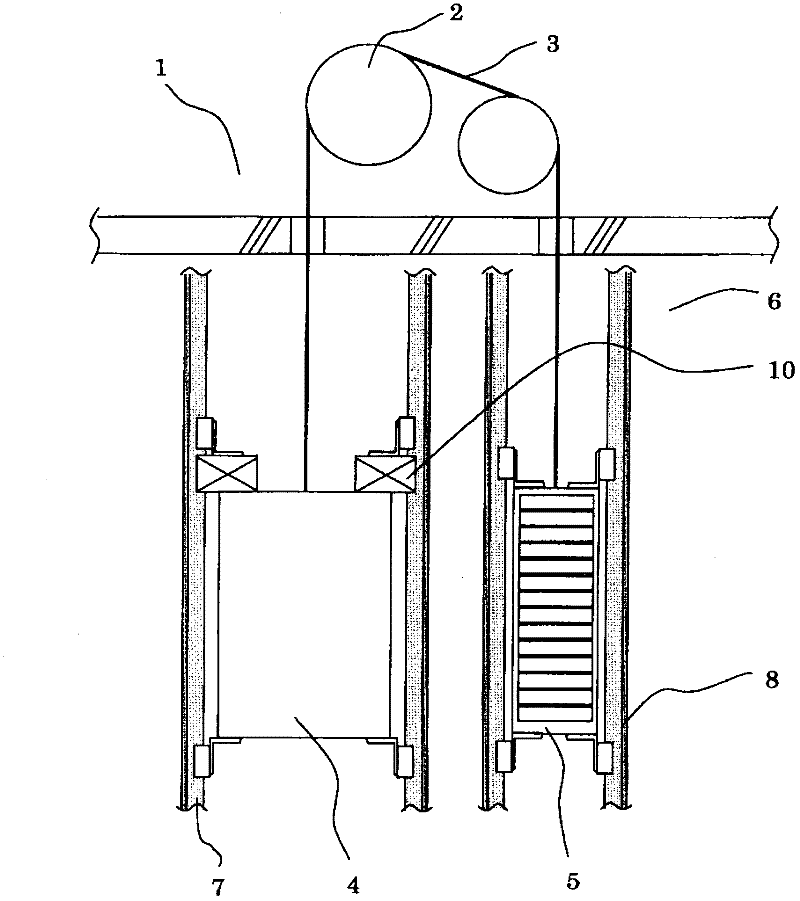
[0062] Such as figure 1 As shown, in the elevator, the pulley 2 of the hoist installed in the machine room 1 is wound with a sling 3 , and the elevator car 4 and the counterweight 5 are respectively connected to the two ends of the sling 3 . In the elevator passage 6, the elevator car 4 is guided by the car side guide rail 7, and the counterweight 5 is guided by the counterweight side guide rail 8. By rotating the pulley 2 of the hoist, the elevator car 4 and the counterweight 5 are in the elevator passage 6. lift inside. In addition, the braking device 10 of this embodiment is fixed to the upper portion of the elevator car 4 with unillustrated bolts.

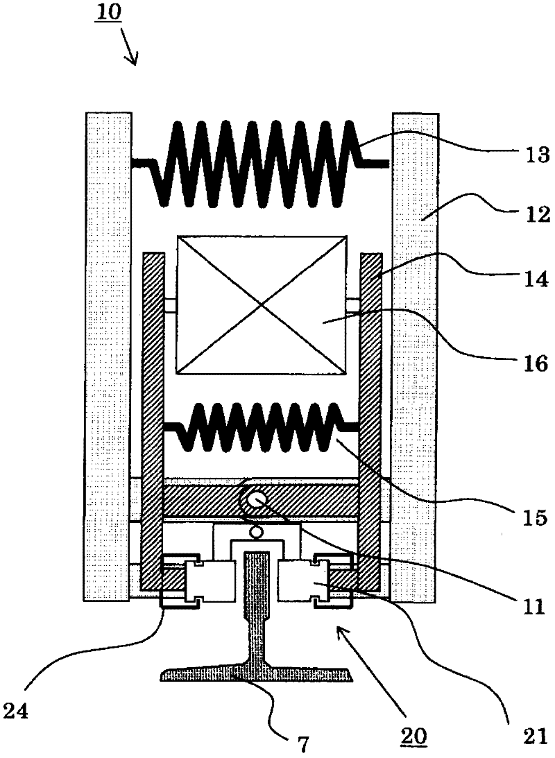
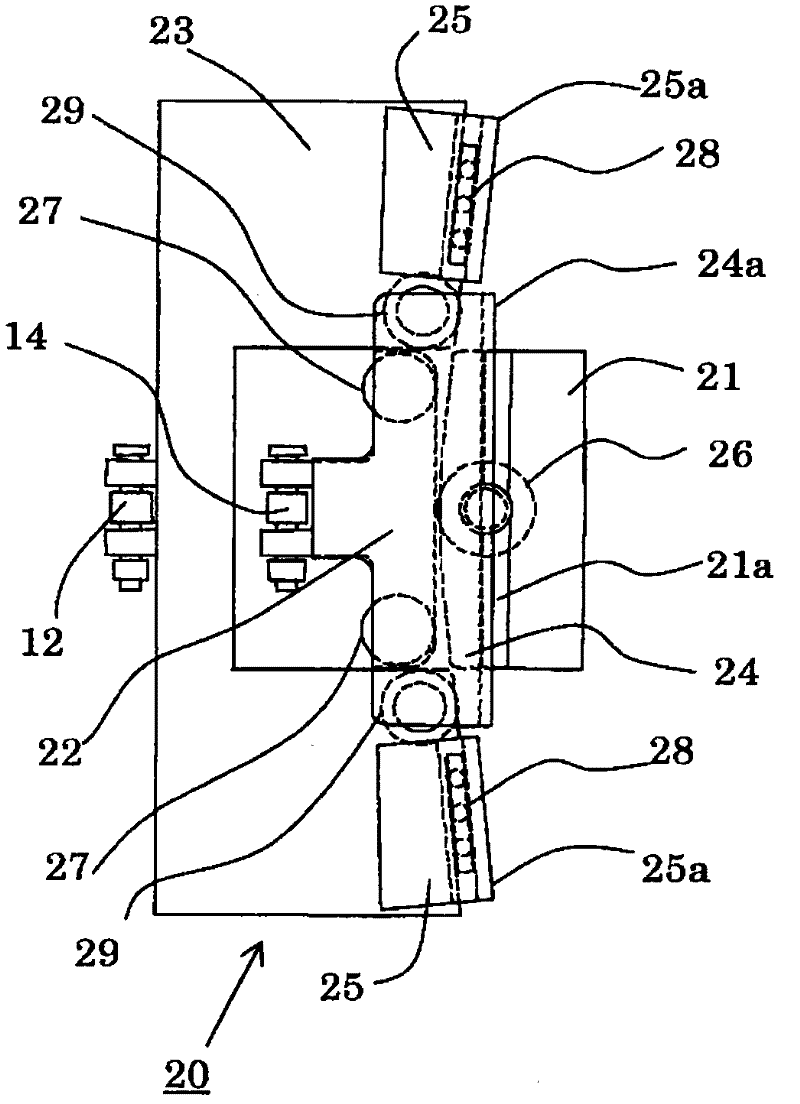
[0063] Such as Figure 2 to Figure 6 As shown, the brake device 10 of this embodiment has: brake arms 12, which are arranged in pairs in an opposing manner, and are arranged to be...


PUM


Abstract

The invention provides a brake device of an elevator, wherein a brake member can move along a brake body smoothly when the elevator is braked. The brake device of the elevator brakes the elevator in elevating, and possesses the brake member, an action body and the brake body. The brake member moves upward when the elevator falls down through the friction force pressed on the body to be braked, and moves downward when the elevator moves rises. The action body is arranged at the surface opposite to the brake surface of the brake body, when the brake device is power-off, the brake member moves toward the direction of the body to be braked. The brake body possesses two inclined surfaces approximately parallel to the inclined surface of the brake member, wherein a plurality of rollers are arranged between the brake member and the action body, and between the brake member and the brake body, thereby when the brake member moves up and down, the direct contact is prevented.

Description

technical field [0001] The present invention relates to a braking device for an elevator, in particular to a braking device for an elevator that uses an actuator to brake the lifting body when the lifting speed exceeds a specified value or when the lifting body is running in an uncontrolled state. moving device. Background technique [0002] As a device that uses an actuator to brake an elevating body, there is known a brake device that has an actuator and a brake member. When the power supply of the lower actuator is disconnected, the braking member slides into contact with the braking body through elastic force, thereby decelerating and stopping the lifting body. In addition, the technology of using the above-mentioned device using the actuator as a device for braking the lifting body can also be cited. When the lifting speed exceeds a predetermined value, or when the lifting body is running in an uncontrolled state, the technology is used to brake the lifting body. The ...

Claims


Application Information

Patent Timeline
Patent Type & Authority Applications(China)
IPC IPC(8): B66B5/22
Inventor 羽田诚秀平野薰座间秀隆酒井悠至
Owner HITACHI LTD
Why Eureka
Try Eureka