Steel wire rope rear deformer

A deformer and steel wire rope technology, applied in the mechanical field, can solve the problems of easily scratched steel wire ropes, difficult to adjust the distance, etc., and achieve the effect of simple structure and convenient adjustment

Inactive Publication Date: 2012-01-25
江苏宏泰不锈钢丝绳有限公司
View PDF0 Cites 6 Cited by
  • Summary
  • Abstract
  • Description
  • Claims
  • Application Information

AI Technical Summary

Problems solved by technology

[0003] The technical problem to be solved in the present invention is that the traditional steel wire rope rear deformer is not easy to adjust the spacing, and it is easy to scratch the steel wire rope used as decoration

Method used


Image

  • Steel wire rope rear deformer
  • Steel wire rope rear deformer
  • Steel wire rope rear deformer

Examples


Embodiment Construction

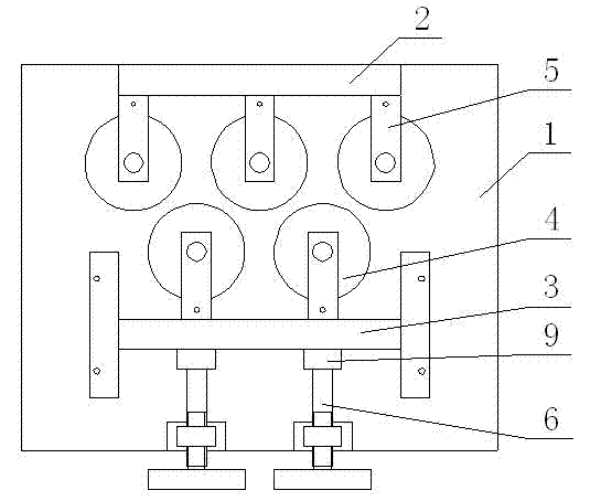
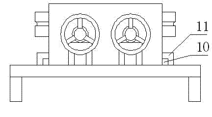
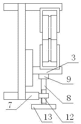
[0011] As shown in the figure, the wire rope rear deformer of the present invention includes a base 1, an upper pressing plate 2, a lower pressing plate 3, two rows of deformation pulleys 4, and an adjustment device 6, and the upper pressing plate 2 is fixed on the base 1, and the The lower pressing plate 3 is arranged parallel to the upper pressing plate 2 on the base 1, the bottom of the lower pressing plate 3 is provided with a bump 10, and the corresponding position of the base 1 is provided with a sliding groove 11 to cooperate with the bump 10 , the lower platen 3 can move up and down along the base 1, a row of U-shaped brackets 5 are respectively arranged on the opposite sides of the upper platen 2 and the lower platen 3, and the bottom of the U-shaped brackets 5 is fixed on the upper platen 2 or the lower platen 3, and the adjacent U-shaped brackets in the two rows of U-shaped brackets 5 are staggered up and down, the deformation pulley 4 is installed in the groove o...


PUM


Abstract

The invention discloses a steel wire rope rear deformer. An upper pressure plate is fixed on a base. A lower pressure plate and the upper pressure plate are arranged in parallel on the base. The opposite lateral surfaces of the upper and lower pressure plates are respectively provided with a row of U-shaped brackets and the two rows of U-shaped brackets are arranged up and down in an adjacent staggered mode. Deformation pulleys are arranged in grooves of the U-shaped brackets and freely rotate. A regulating device drives the lower pressure plate to move up and down along the base. The regulating device comprises a bracket, a regulating rod and a fixed frame. The fixed frame is fixed on the outer lateral surface of the lower pressure plate. The bracket is fixed on the base. The upper end of the bracket is provided with a screwed hole. The regulating rod passes through the screwed hole on the bracket. One end of the regulating rod is arranged in the fixed frame and the other end of the regulating rod is provided with a rotating handle. The regulating rod is vertical to the lower pressure plate. The position on the regulating rod, which corresponds to the bracket, is provided with an external screw thread which is matched with the screwed hole. The steel wire rope rear deformer disclosed by the invention has a simple structure, is convenient to regulate and has wear resistance and deformation resistance. Moreover, a steel wire rope for decoration cannot be scratched.

Description

technical field [0001] The invention belongs to the field of machinery, in particular to a steel wire rope rear deformer. Background technique [0002] In the process of producing steel wire rope, the twisted steel wire rope will produce stress, which will cause the bending of the steel wire rope. Therefore, in the production of steel wire rope, the steel wire rope post-deformer should be used to straighten the steel wire rope and eliminate the stress. The upper and lower pressure plates of the traditional steel wire rope rear deformer are fixed on the base, which makes it difficult to adjust the spacing, and the deformation pulley is an iron wheel, which is easy to scratch the decorative steel wire rope. Contents of the invention [0003] The technical problem to be solved by the present invention is that the traditional steel wire rope rear deformer is not easy to adjust the spacing, and it is easy to scratch the decorative steel wire rope. [0004] In order to so...

Claims


Application Information

Patent Timeline
Patent Type & Authority Applications(China)
IPC IPC(8): D07B7/02
Inventor 陈爱红赵五平徐春林董德元
Owner 江苏宏泰不锈钢丝绳有限公司
Why Eureka
Try Eureka