Capacitor installing stack structure and installing method of capacitor

A technology of stacking structures and capacitors, which is applied in the direction of capacitors and electrical components, etc., can solve problems such as unspecified size correspondence, and achieve the effects of shortening the height and position alignment time, improving the installation height and position alignment accuracy, and reducing installation operations

Active Publication Date: 2012-01-25
FUJI ELECTRIC CO LTD
View PDF5 Cites 4 Cited by
  • Summary
  • Abstract
  • Description
  • Claims
  • Application Information

AI Technical Summary

Problems solved by technology

[0008] In the conventional method for realizing the stacked structure as described above, since a lot of labor and work are required, there is a problem that the predetermined size cannot be easily matched.

Method used


Image

  • Capacitor installing stack structure and installing method of capacitor
  • Capacitor installing stack structure and installing method of capacitor
  • Capacitor installing stack structure and installing method of capacitor

Examples


Embodiment Construction

[0028] Embodiments of the present invention will be described in detail below.

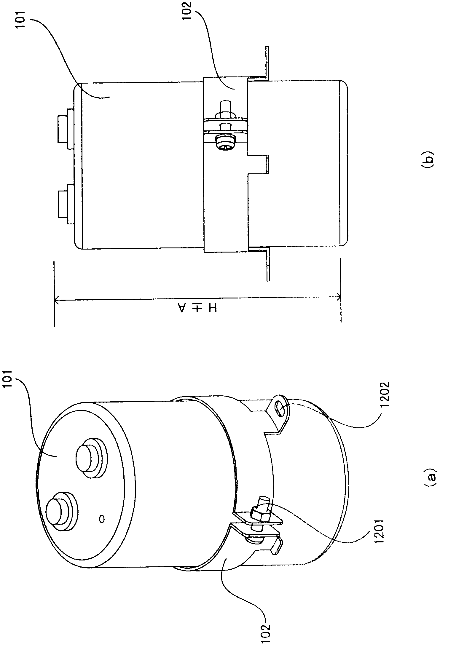
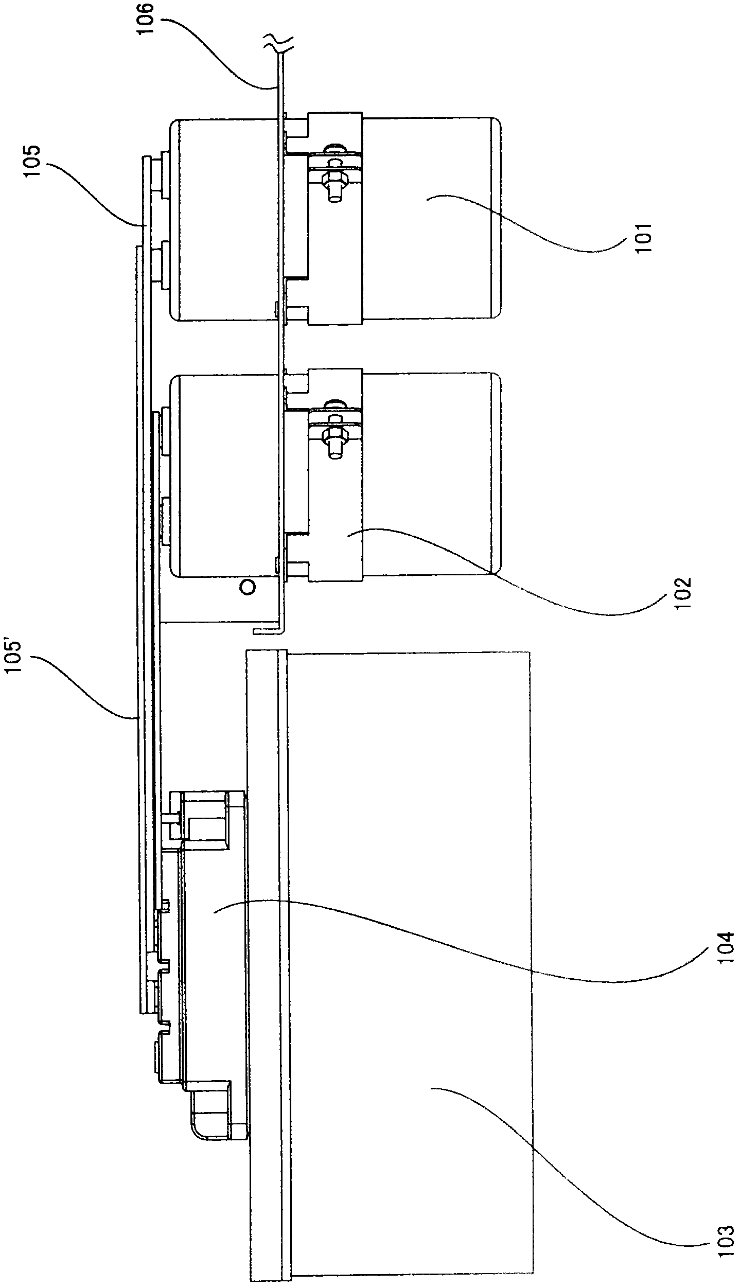
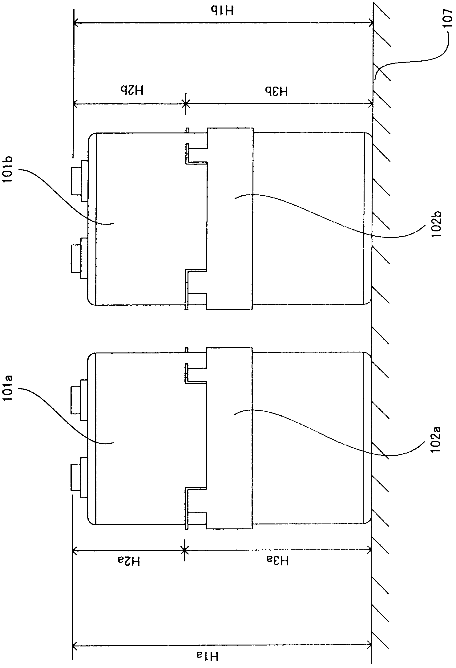
[0029] Figure 4 It is a figure which shows the structure of the capacitor mounting stack structure which concerns on embodiment of this invention, (a) is a back perspective view seen from the left side, (b) is a top view, (c) is a front perspective view seen from the right side, (d) is a rear view, and (e) is a right side view. From Figure 4 It can be seen that the capacitor mounting table 108 is composed of a large L-shaped bent metal plate, and on the left and right of the metal plate, there are provided jigs 109 for achieving height and dimensional accuracy during capacitor mounting by further bending. In addition, a hole for inserting the capacitor 101 is opened in the metal plate constituting the capacitor mounting stand 108 , and the capacitor 101 is inserted through the hole and fixed to the fixing fitting 102 by using a fastening device such as a screw in this state. At this time, ins...


PUM


Abstract

The present invention provides a capacitor installing stack structure, wherein a capacitor installing platform is reversedly arranged on an operating platform, thus clamping parts arranged at left and right side of the capacitor installing platform can play a clamping function to ensure a specified size H2T defined by the clamping parts, then the capacitor is inserted into an installing hole of the capacitor installing platform which is reversedly arranged when in a reversal state, thus a distance H2C from the horizontal operating platform to a terminal arranged at an upper part of the capacitor can be set as the same with the specified size H2T defined by the clamping parts. Under the state, the capacitor can be fixed on the capacitor installing platform by using fixing parts.

Description

technical field [0001] The present invention relates to a capacitor that can be mounted without worrying about the dimensional error in the height direction of the capacitor (for smoothing) that is allowed at the manufacturing stage in a power conversion device configured by interconnecting a plurality of semiconductor modules and a plurality of capacitors with laminated conductors Mounting methods for mounting stacked structures and capacitors. Background technique [0002] figure 1 (a) shows the shape of a general capacitor (for smoothing) and the structure used to fix the capacitor when the capacitor is mounted (assembled) in a power conversion device configured by connecting a plurality of semiconductor modules and a plurality of capacitors with laminated conductors. A diagram of a structural example of a fixing fitting (fixing metal fitting). exist figure 1 In (a), each capacitor 101 includes a terminal connected to a conductor at its upper portion, and a fixing fitt...

Claims


Application Information

Patent Timeline
Patent Type & Authority Applications(China)
IPC IPC(8): H01G2/02
Inventor 山方义彦我妻裕
Owner FUJI ELECTRIC CO LTD
Why Eureka
Try Eureka