Atmospheric plasma device and manufacturing method thereof

An atmospheric pressure plasma and plasma technology, applied in the direction of plasma, electrical components, etc., can solve the problems of difficulty in removing, reducing the life of the device, corrosion of the cathode insulating medium, etc., and achieve the effect of improving cleaning uniformity, improving life, and reducing corrosion.

Active Publication Date: 2013-01-02
TCL CHINA STAR OPTOELECTRONICS TECH CO LTD
View PDF0 Cites 0 Cited by
  • Summary
  • Abstract
  • Description
  • Claims
  • Application Information

AI Technical Summary

Problems solved by technology

[0007] (1) The circular design method is adopted, which does not take into account the equal design of the plasma generation area and the plasma exclusion area, which will easily cause the plasma to easily stay between the anode and the cathode, corrode the cathode and the insulating medium, and reduce the life of the device;
[0008] (2) Adopting the Chidori arrangement, the position of the plasma exclusion area and the position of the plasma generation area are not equidistant, and the plasma close to the plasma exclusion area is easy to exclude, but the plasma far away from the plasma exclusion area is not easy to exclude, so that the plasma in the local area is easy stagnation, while the plasma concentration near the plasma exclusion area on the outside of the cathode is higher, and the plasma concentration farther away from the plasma exclusion area is lower, resulting in uneven distribution of plasma and poor uniformity of surface treatment

Method used


Image

  • Atmospheric plasma device and manufacturing method thereof
  • Atmospheric plasma device and manufacturing method thereof
  • Atmospheric plasma device and manufacturing method thereof

Examples


Embodiment Construction

[0029] The present invention will be described in detail below in conjunction with the accompanying drawings and embodiments.

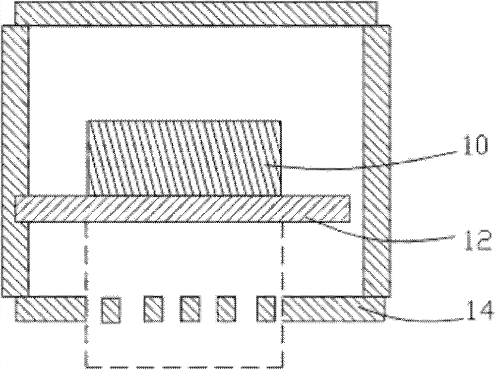
[0030] refer to figure 2 , and see in conjunction with image 3 , is a structural schematic diagram of the first embodiment of the atmospheric pressure plasma device of the present invention, the atmospheric pressure plasma device includes: an anode 10, an insulating medium 12 and a cathode 14, the cathode 14 refers to the part facing the anode 10 with the insulating medium 12 separated, and the positive The partial area of ​​the pair is equal to the area of ​​the anode 10 .

[0031] The insulating medium 12 is disposed between the anode 10 and the cathode 14 .

[0032] An ionizable gas is filled between the anode 10 and the cathode 14 .

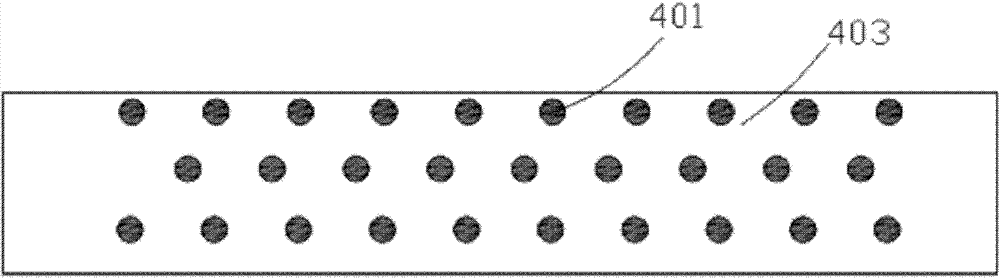
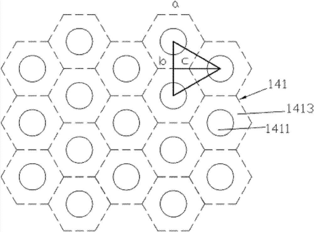
[0033]The cathode 14 includes a plurality of uniformly distributed identical plasma generation and removal units 141 . The above-mentioned plasma generation and exclusion unit 141 naming is determined for conve...


PUM


Abstract

Provided are an atmospheric pressure plasma device and a process for manufacturing the same. The atmospheric pressure plasma device comprises an anode, a cathode, and an insulating medium provided between the anode and the cathode; the space between the anode and the cathode is filled with an ionizable gas; the cathode comprises a plurality of plasma generating and discharging units, with each plasma generating and discharging unit comprising a plasma discharging region and a plasma generating region; the plasma discharging region is surrounded by the plasma generating region, and the plasma discharging region has the same area as the plasma generating region; among three plasma discharging regions adjacent to each other, any two of the plasma discharging regions have the same distance between their centres. The above method can reduce the corrosion by plasma to the cathode and the insulating medium, enhance the life of the atmospheric pressure plasma device, and moreover, can increase the cleanliness and uniformity of the substrate surface.

Description

technical field [0001] The invention relates to the field of plasma display panel manufacturing, in particular to an atmospheric pressure plasma device and a manufacturing method thereof. Background technique [0002] As matter is continuously given energy, it heats up and changes from solid to liquid and then to gas. Continued application of energy results in a further change of state in which neutral atoms or molecules of the gas undergo high-energy collisions to produce negatively charged electrons, positive or negative ions, and other species. This mixture of charged species exhibits a collective behavior known as a "plasma". [0003] Atmospheric pressure plasma treatment as a new surface treatment technology, such as plasma cleaning, has low temperature and normal pressure treatment, will not cause damage to the material surface, no arc, no vacuum chamber, no harmful gas suction system, long-term use and It has many advantages such as no physical damage to the operato...

Claims


Application Information

Patent Timeline
Patent Type & Authority Patents(China)
IPC IPC(8): H05H1/24
CPCH05H2001/2412H05H1/2406H05H2245/123H05H2245/40
Inventor 严茂程施翔尹
Owner TCL CHINA STAR OPTOELECTRONICS TECH CO LTD
Why Eureka
Try Eureka