Grinding machine crankshaft machining counter weight device

A technology for crankshaft processing and counterweight device, which is applied in grinding machines, metal processing equipment, and machine tools designed for grinding the rotating surface of workpieces, etc. Easy to install and easy to use effect

Inactive Publication Date: 2013-04-17
NFC (SHENYANG) METALLURGICAL MACHINERY CO LTD
View PDF9 Cites 0 Cited by
  • Summary
  • Abstract
  • Description
  • Claims
  • Application Information

AI Technical Summary

Problems solved by technology

[0003] 1. First, the eccentric chuck 104 is connected to the centering top plate 103 through connection, and the centering top plate 103 is then fixed to the machine bed 106 through pin positioning. This repeated positioning and closing process will inevitably result in the accumulation of tolerances , affecting the machining accuracy of the eccentric crankshaft 105;
[0004] 2. Since the eccentric chuck 104 adopts an L-shaped structure, which is long and thick in the axial direction, it is easy to generate tension on both sides when it is installed and used. Axis consistent;
[0005] 3. When the jig is used to process the eccentric crankshaft 105, according to the principle of leverage, due to the weight of the eccentric crankshaft 105 itself and the cutting force generated by the tool during processing, the eccentric crankshaft 105 will deflect downwards to varying degrees, seriously affecting the eccentric crankshaft 105 processing quality;
[0006] 4. For the L-shaped eccentric chuck 104 with too long cantilever, as the length of the processed eccentric crankshaft 105 is lengthened, the shaft diameter increases, and the weight increases, the stability gradually weakens, resulting in a gap between the processed three-throw crankshaft and the three-throw crankshaft. The coaxiality is not parallel, which seriously affects the normal transmission torque of the eccentric crankshaft 105;
[0007] 5. Since the counterweight 101 is respectively installed on both sides of the head of the machine tool 107 and the end of the machine 102, according to the principle of moment balance, the force transmission distance is virtually increased, resulting in poor machining stability of the eccentric crankshaft 105, which affects the machining accuracy
[0008] Now there is also a machining center for grinding the eccentric crankshaft 105, but the machining center is suitable for the processing of the short eccentric crankshaft 105, and the investment is large

Method used


Image

  • Grinding machine crankshaft machining counter weight device
  • Grinding machine crankshaft machining counter weight device
  • Grinding machine crankshaft machining counter weight device

Examples


Embodiment Construction

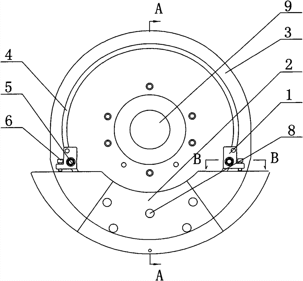
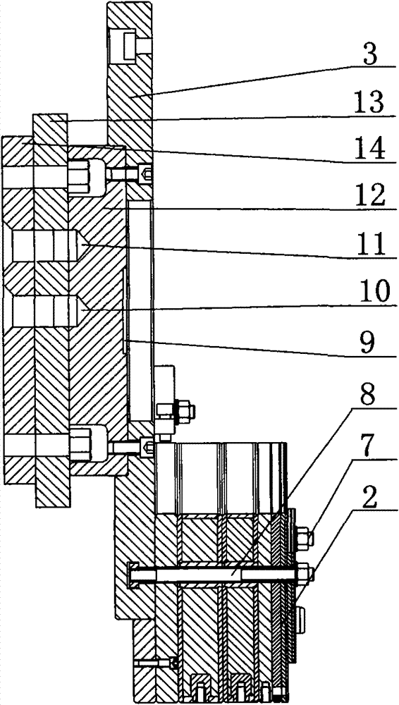
[0023] The present invention comprises centering top plate 13, and the side of centering top plate 13 is provided with eccentric mounting plate 12, eccentric balance plate 3 in sequence, and the outer side of one end of eccentric balance plate 3 is provided with arc-shaped counterweight balance plate 2, and the arc-shaped counterweight balance plate 2 is The heavy balance plate 2 is fixed on the eccentric balance plate 3 through bolts 8 and nuts 7 on the eccentric balance plate 3 .

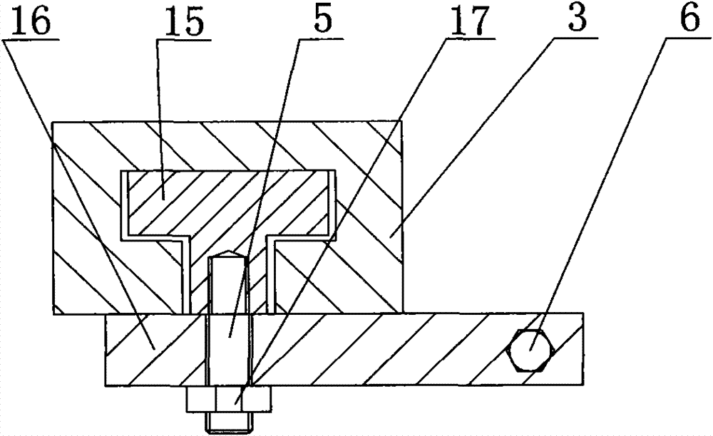
[0024] On both sides of the eccentric balance plate 3 above the arc-shaped counterweight balance plate 2, a fine-tuning mechanism 1 is respectively arranged; the fine-tuning mechanism 1 includes an arc-shaped groove 4 on the eccentric balance plate 3, and the cross-section of the arc-shaped groove 4 is T-shaped. The T-shaped block 15 in the arc groove 4 is provided with an adjusting bolt 5, and the baffle plate 16 is fixed between the compression nut 17 of the adjusting bolt 5 and the eccentric bal...


PUM


Abstract

The invention discloses a grinding machine crankshaft machining counter weight device, belongs to improvement of the grinding machine crankshaft machining counter weight device, and provides the grinding machine crankshaft machining counter weight device which is more suitable for machining a long eccentric crankshaft, has high machining quality and is convenient to use. The device comprises a centric pressing disc, and has the structural key points that: the centric pressing disc is laterally and sequentially provided with an eccentric mounting disc and an eccentric balance disc; and a cambered counter weight balancing plate is arranged outside one end of the eccentric balance disc and is fixed on the eccentric balance disc through bolts and nuts on the eccentric balance disc.

Description

Technical field: [0001] The invention belongs to the improvement of a grinding machine crankshaft processing counterweight device. Background technique: [0002] At present, the grinding process of the eccentric crankshaft 105 of the domestic diaphragm pump is usually carried out by using an additional counterweight 101 on a common grinding machine. Its method is that the eccentric crankshaft 105 is respectively fixed on the positive center top plate 103 of the head of the bed 107 and the tail of the bed 102 by the L-shaped eccentric chuck 104, and counterweights 101 are respectively arranged on the main shafts of the outer ends of the head of the bed 107 and the tail of the bed 102. But there are following disadvantages: [0003] 1. First, the eccentric chuck 104 is connected to the centering top plate 103 through connection, and the centering top plate 103 is then fixed to the machine bed 106 through pin positioning. This repeated positioning and closing process will inev...

Claims


Application Information

Patent Timeline
Patent Type & Authority Patents(China)
IPC IPC(8): B24B5/42B24B5/35
Inventor 刘红枫赵志徐雁凯杨志
Owner NFC (SHENYANG) METALLURGICAL MACHINERY CO LTD
Why Eureka
Try Eureka