Liquid container and liquid ejection system

A liquid storage container and liquid technology, applied in printing and other directions, can solve problems such as ink leakage, air introduction into ink tanks, and reduced air permeability of sheet parts

Active Publication Date: 2012-02-01
SEIKO EPSON CORP
View PDF10 Cites 32 Cited by
  • Summary
  • Abstract
  • Description
  • Claims
  • Application Information

AI Technical Summary

Problems solved by technology

Once the sheet member is wetted with ink, the sheet member loses its original function, so that ink sometimes leaks through the sheet member
In addition, the air permeability of the sheet member may decrease, and air may not be introduced into the ink tank from the opening to the atmosphere.
In addition, this problem exists not only in the ink tank, but also in the liquid storage container for storing the liquid ejected by the liquid ejection device inside, that is, the liquid storage container provided with a liquid injection port and an air release port, respectively.

Method used


Image

  • Liquid container and liquid ejection system
  • Liquid container and liquid ejection system
  • Liquid container and liquid ejection system

Examples


no. 1 example

[0053] B-1-1. Structure of Liquid Injection System:

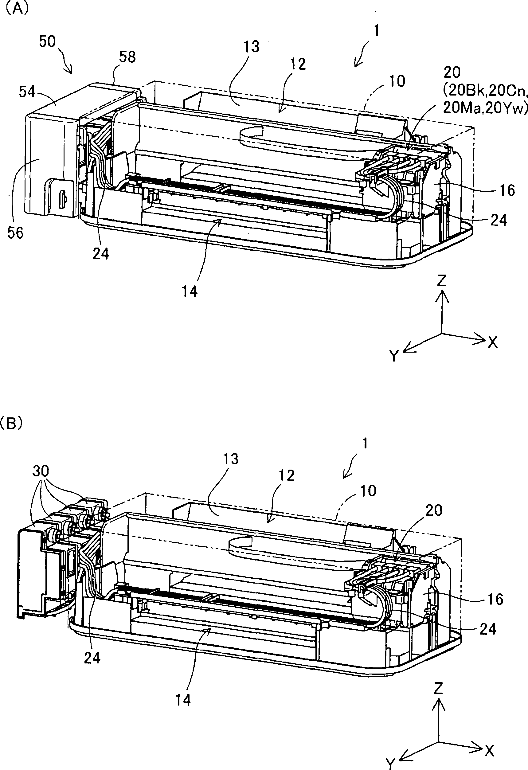
[0054] figure 2 It is a diagram for explaining the liquid ejection system 1 of the first embodiment. figure 2 (A) is an external perspective view of the liquid ejection system 1 . figure 2 (B) is an external perspective view of the liquid ejection system 1, showing the liquid storage container 30 of the first embodiment of the present invention.

[0055] Such as figure 2 As shown in (A), the liquid ejection system 1 includes an inkjet printer 12 (abbreviated as “printer 12 ”) as a liquid ejection device, and a tank unit 50 . The printer 12 includes a paper feed unit 13 , a paper discharge unit 14 , a carriage 16 and four sub tanks 20 . The four sub-tanks 20 store inks of different colors. Specifically, the four sub-tanks 20 are a sub-tank 20Bk for storing black ink, a sub-tank 20Cn for storing cyan ink, a sub-tank 20Ma for storing magenta ink, and a sub-tank 20Yw for storing yellow ink. Four sub-tanks 20 are mount...

no. 2 example

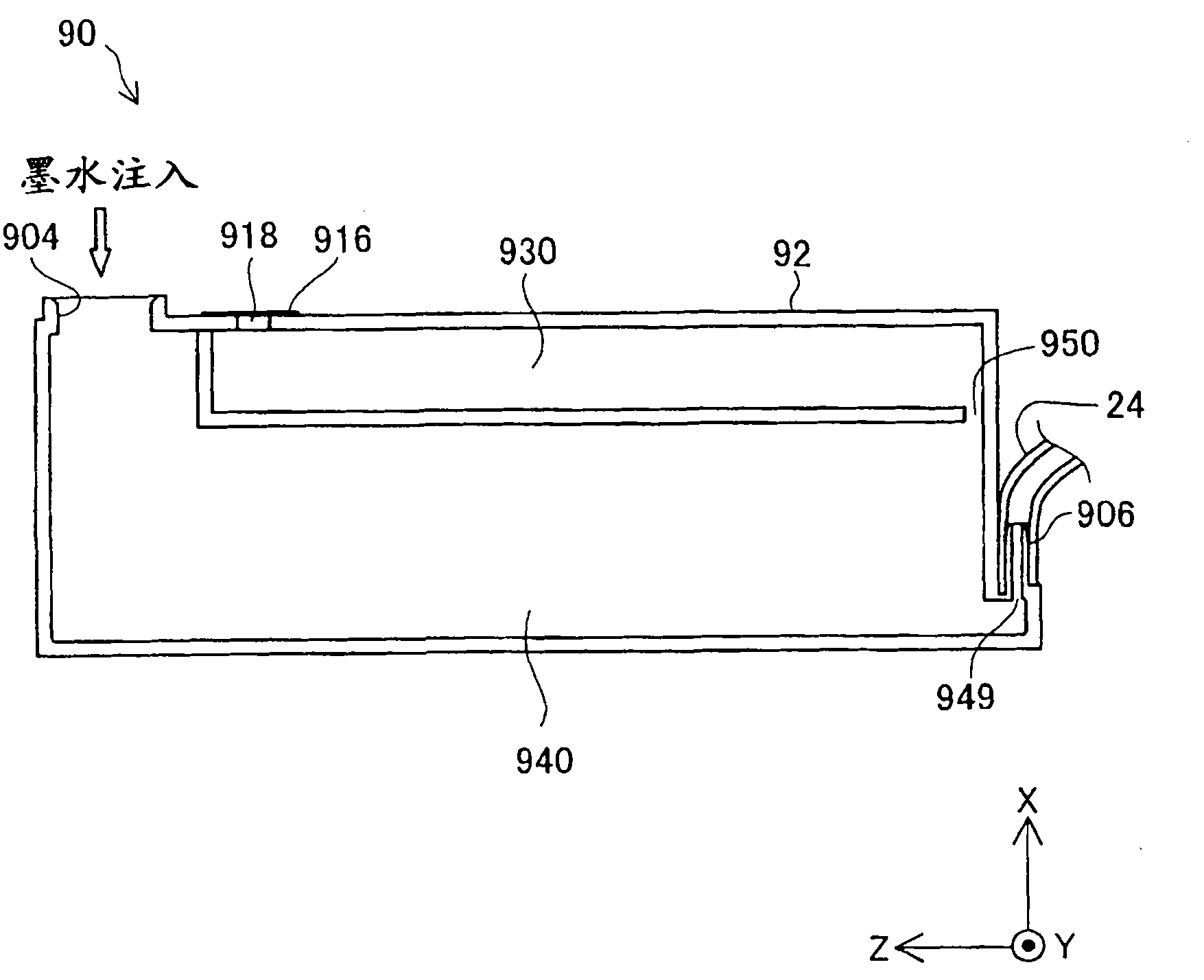
[0095] Figure 11 It is a diagram for explaining the ink tank 30a of the second embodiment. Figure 11 (A), (B) are the same as the first embodiment Figure 7 (A) Corresponding graph. Figure 11 (B) is a figure for explaining the state of the ink tank 30a when the injection amount of ink is too much. The difference from the ink tank 30 of the first embodiment lies in the structure of the liquid storage chamber 340a and the height position of the liquid injection port 304a in the injection posture. The other structures are the same as those of the first embodiment, so the same reference numerals are assigned and explanations are omitted. In addition, the ink tank 30a of the second embodiment is also used in the liquid ejection system 1 ( figure 2 ). Also, for ease of understanding, Figure 11 In (A), the plug member 302 is shown by a dotted line.

[0096] Such as Figure 11 As shown in (A), the liquid injection port 304 a is formed in the tank body 32 so as to be lower...


PUM


Abstract

The invention provides a liquid container and a liquid ejection system. A technology is provided, in the liquid container respectively provided with a liquid injection port and an atmospheric vent, possibility of liquid spill from the atmospheric vent when the liquid is injected from the liquid injection port to the liquid container can be reduced. Disclosed is a liquid container for supplying a liquid to a liquid ejection device, said liquid container being provided with: a liquid storage chamber for storing the liquid; an air storage chamber which communicates with the liquid storage chamber, and which is for introducing external air into the liquid storage chamber as the liquid in the liquid storage chamber is consumed; an atmospheric vent which introduces external air into the air storage chamber; and a liquid injection port which is for injecting the liquid into the liquid storage chamber, and which is disposed at a lower position than the atmospheric vent when the liquid container is in an injection position when the liquid is to be injected into the liquid storage chamber.

Description

technical field [0001] The present invention relates to a liquid storage container and a liquid ejection system provided with the liquid storage container. Background technique [0002] A printer as an example of a liquid ejecting device ejects ink from a recording head onto a recording object (for example, printing paper) to perform printing. As an ink supply technique to the recording head, there is known a technique in which ink is supplied to the recording head from an ink cartridge disposed on the recording head, and at the same time, the ink is supplied to the ink cartridge or the head via a tube from an ink tank disposed outside the liquid ejecting device. A technique for partially supplying ink (for example, refer to Patent Documents 1 to 3). Ink tanks hold larger amounts of ink than ink cartridges. In addition, the ink tank has an ink inlet, and the user can easily inject ink (refill) from the ink inlet. [0003] For example, in the technique of Patent Document 1...

Claims


Application Information

Patent Timeline
Patent Type & Authority Applications(China)
IPC IPC(8): B41J2/175
CPCB41J2/17503
Inventor 清水芳明石泽卓武田侑希
Owner SEIKO EPSON CORP
Why Eureka
Try Eureka