High-pressure inflating pump structure

A technology of air pumps and high-pressure gas cylinders, which is applied in the direction of liquid displacement machines, machines/engines, mechanical equipment, etc. It can solve the problems of high manufacturing costs, bending deformation damage of puncture parts 45, and low surface accuracy, so as to save resources Effect

Inactive Publication Date: 2012-02-01
黄英哲 +1
View PDF5 Cites 5 Cited by
  • Summary
  • Abstract
  • Description
  • Claims
  • Application Information

AI Technical Summary

Problems solved by technology

[0003] However, although the structure of the known CO2 inflator 40 can quickly inflate the high-pressure gas in the high-pressure CO2 cylinder 30 to inflate the tires, the structure of the known CO2 inflator 40 needs to spend a considerable amount of time because the structure is too complicated. manufacturing cost, and the piercing member 45 is a shaft extending from top to bottom. Mass-manufactured consumable products, based on cost considerations, have low surface precision in manufacturing, so the straightness of the end face 311 is not good and often has irregular curved arcs. In the process of piercing the end face 311 by the part 452, the piercing part 45 may be formed during the piercing process because the end face 311 is too uneven. Damage caused by bending deformation of piece 45

Method used


Image

  • High-pressure inflating pump structure
  • High-pressure inflating pump structure
  • High-pressure inflating pump structure

Examples


Embodiment Construction

[0049] In order to have a clearer understanding of the technical features, purposes and effects of the present invention, the specific implementation manners of the present invention will now be described with reference to the accompanying drawings.

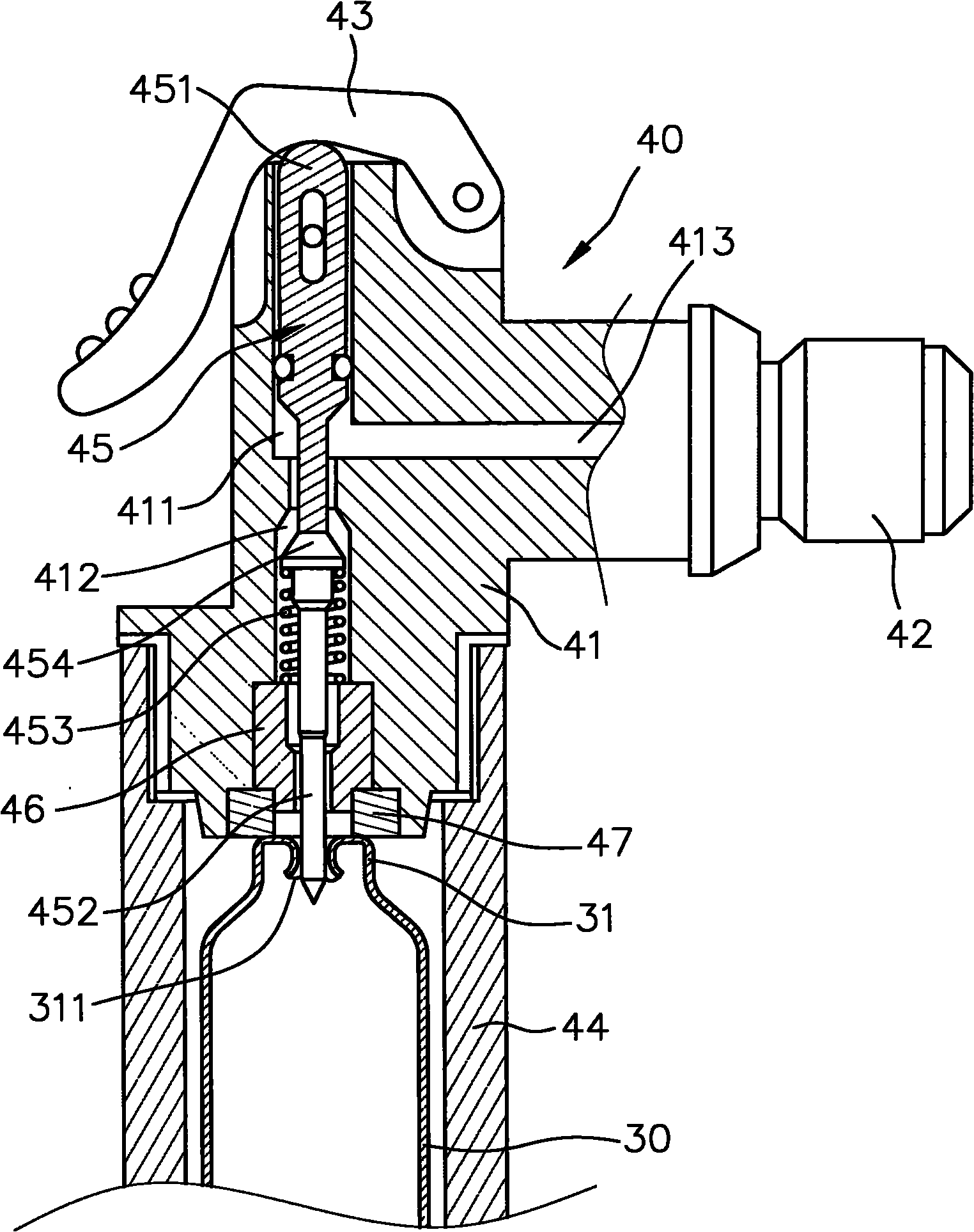
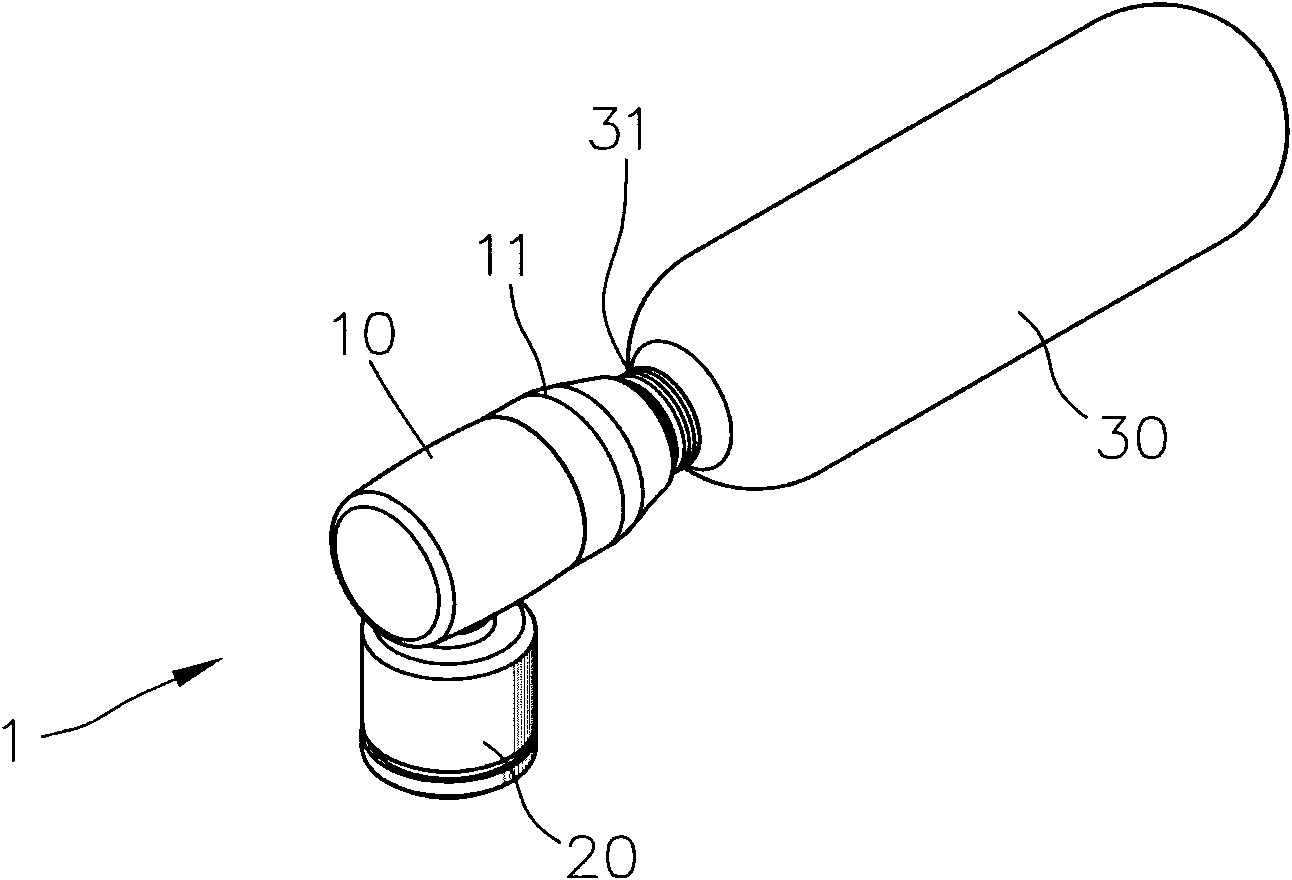
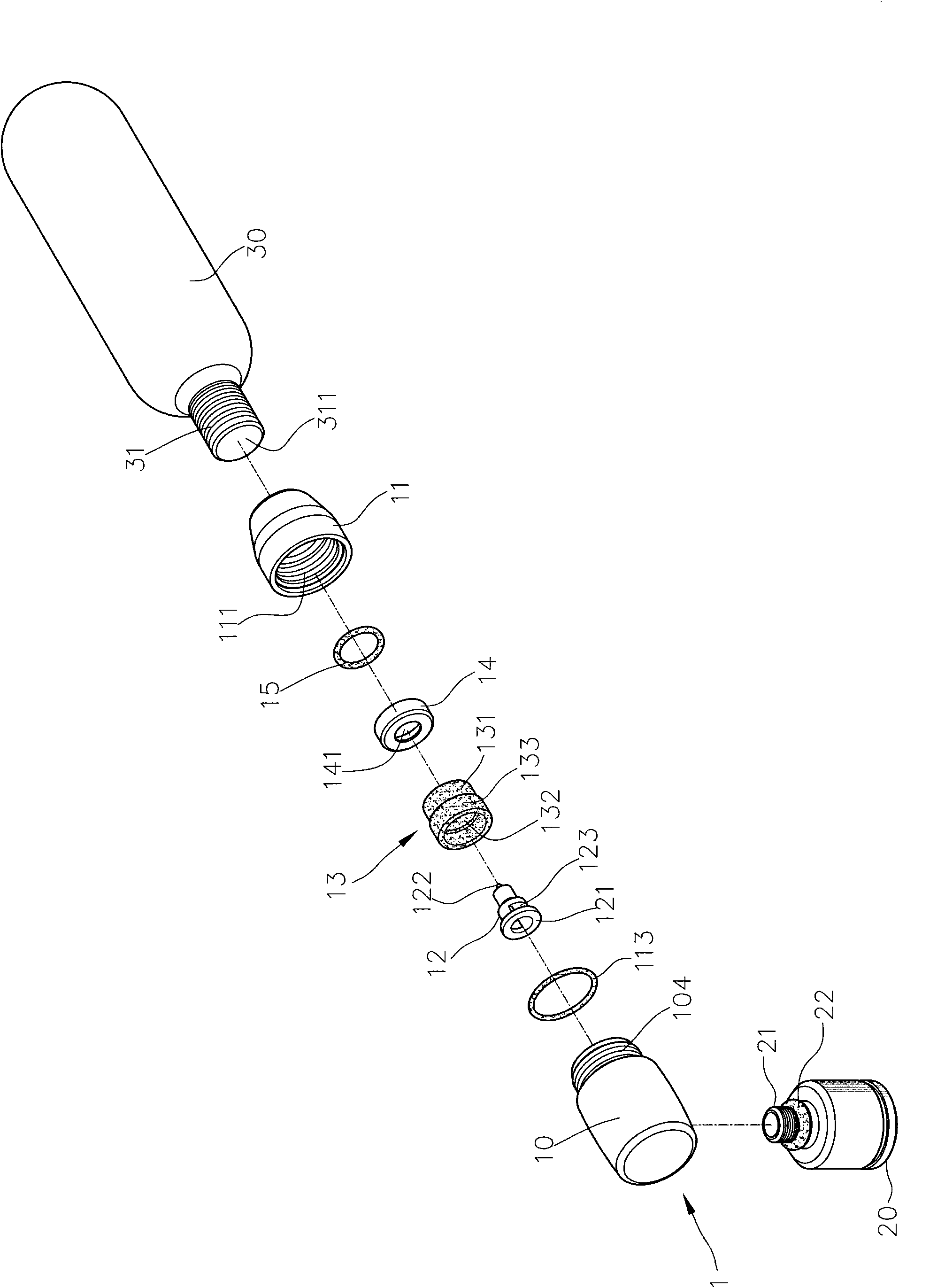
[0050] see figure 2 , image 3 and Figure 4 The structural design of the preferred embodiment of the present invention shown is to solve the problem that the structure of the known CO2 inflator is too complicated, and to effectively maintain the air pressure in the high-pressure gas cylinder 30 such as the CO2 gas cylinder for multiple inflation actions, and to strengthen the The durability of the structure, the high-pressure pump structure of the present invention takes a head 1 as the main body, wherein the head 1 has a first cylinder 10 and a second cylinder 11, and the first cylinder 10 and the second cylinder 11 The opposite ends are provided with threaded parts 104, 111 which can be screwed relative to each other, and a...


PUM


Abstract

The invention provides a high-pressure inflating pump structure which comprises a head, a charging connector, an impaling piece and an elastic piece, wherein the head is provided with a containing part, an air guide channel and a spiral connecting part, the impaling piece is provided with a base, an impaling part and an air guide hole, and the impaling part is provided with a propping ring; the ring surface of the propping ring is close to the end surface so as to form a gas seal state, and the elastic piece is at least provided with a supporting end, a propping top end and a chamber; and thechamber covers on the outer diameter of the impaling piece so as to locate the position of the impaling piece, the gas flow is not blocked to enter the air guide hole, and a tire can be quickly inflated and the structure has the efficacy of reusing a same pressure bottle so as to save resources.

Description

technical field [0001] The invention relates to a high-pressure pump structure, especially a high-pressure gas cylinder that can be filled with high-pressure gas cylinders such as CO2 gas cylinders to quickly inflate tires by releasing high-pressure gas, and has a high-pressure pump that can use the same high-pressure gas cylinder multiple times to save resources. Pump structure. Background technique [0002] see figure 1 As shown in the structure of the known CO2 pump 40, the design focus of the current commercially available CO2 pump structure is to provide a motorcycle or bicycle that can quickly complete the pumping effect, and the CO2 pump 40 has a cylinder body 41, and the cylinder body 41 It is connected with a CO2 high-pressure gas cylinder 30, wherein the cylinder body 41 is provided with a first set-up space 411, a second set-up space 412 and a flow channel 413. In the structure embodiment of the known CO2 pump 40, the flow channel The outer end of the channel 41...

Claims


Application Information

Patent Timeline
IPC IPC(8): F04B33/00
Inventor 黄英哲黄俊铭
Owner 黄英哲
Why Eureka
Try Eureka