Novel structure of convection heating surface of corner tube hot-water boiler

A hot water boiler and heating surface technology, applied in fluid heaters, lighting and heating equipment, etc., can solve problems such as uneven flow rate, avoid sudden changes in cross-section, prevent serious deposition, and save heating surface materials.

Inactive Publication Date: 2012-02-01
SHANGHAI XINYE BOILER HIGH TECH
View PDF1 Cites 4 Cited by
  • Summary
  • Abstract
  • Description
  • Claims
  • Application Information

AI Technical Summary

Problems solved by technology

[0013] The purpose of the present invention is to provide a new structure of the convection heating surface of the corner tu

Method used


Image

  • Novel structure of convection heating surface of corner tube hot-water boiler
  • Novel structure of convection heating surface of corner tube hot-water boiler
  • Novel structure of convection heating surface of corner tube hot-water boiler

Examples


Embodiment Construction

[0023] The present invention will be further described below in conjunction with accompanying drawing.

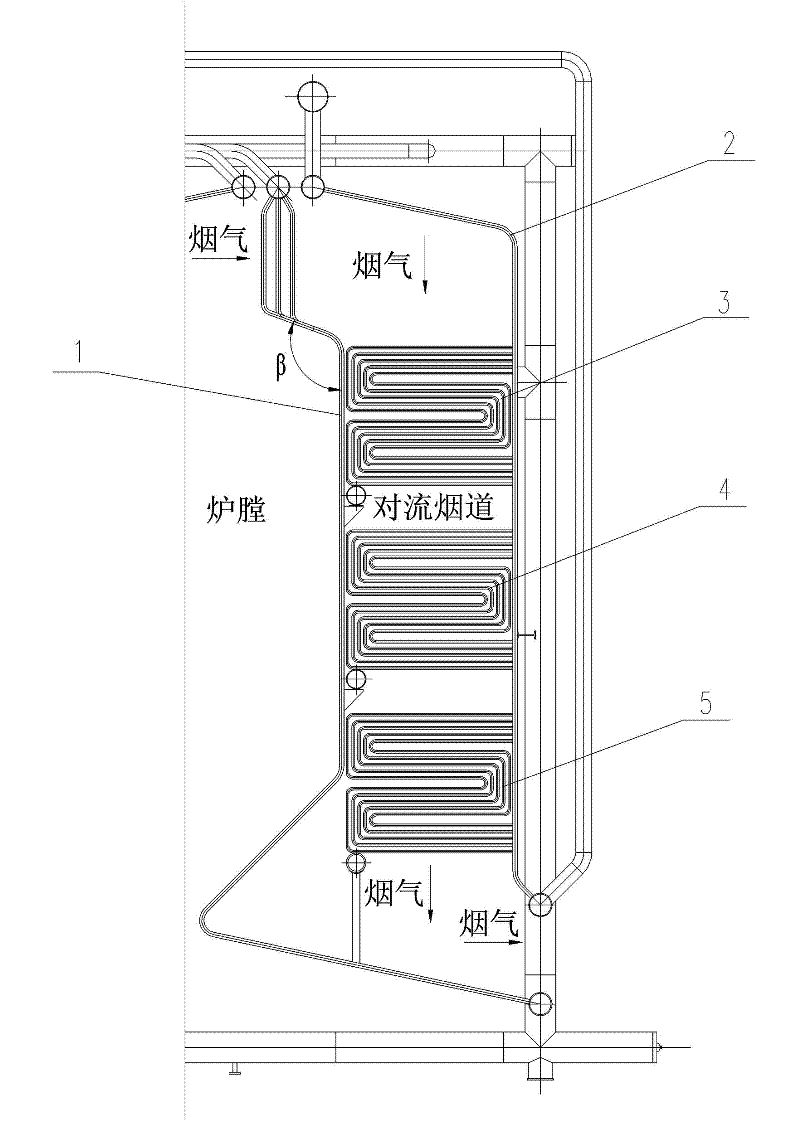
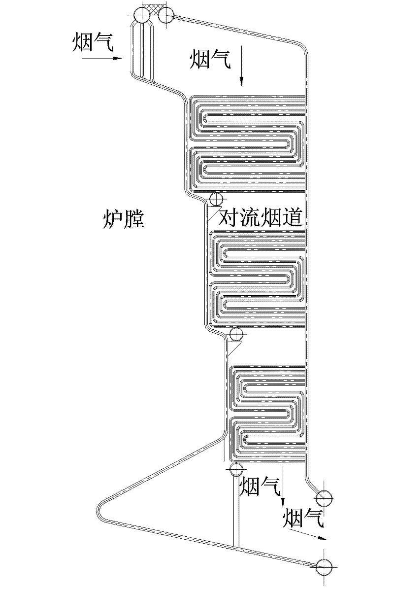
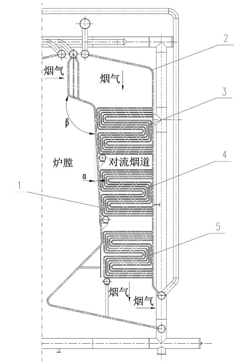
[0024] Such as image 3 Shown: the structure of the convection heating surface of a new type of corner tube hot water boiler of the present invention includes a furnace rear wall 1, a channel rear wall 2, a first-stage flag-type heating surface 3, a second-stage flag-type heating surface 4, The third-stage flag-type heating surface 5 is characterized in that the rear wall of the furnace is simply inclined at an angle α, so that the flue gas flow cross-sectional area of ​​each level of convection heating surface in the convection flue is steadily reduced, so as to realize the flag-type heating of each level in the convection flue. The smoke velocity on the heating surface tends to be consistent. In the specific construction, it is only necessary to add an angle α to the original bending angle β when bending the membrane wall of the rear wall of the furnace. The rest of the m...


PUM


Abstract

The invention discloses a novel structure of a convection heating surface of a corner tube hot-water boiler, which aims to solve the problem that the flow speed at the position of the convection heating surface of a traditional corner tube boiler is uneven. The novel structure of the convection heating surface of the corner tube hot-water boiler comprises a hearth rear wall, a channel rear wall, a first-stage flag type heating surface, a second-stage flag type heating surface and a third-stage flag type heating surface, and is mainly and technically characterized in that the hearth rear wall is purely inclined by an angle alpha, so that the smoke circulating sectional areas of all stages of convection heating surfaces in a convection flue are stably reduced so as to enable the smoke speeds of all the stages of flag type heating surfaces in the convection flue to tend to be consistent. The novel structure of the convection heating surface is mainly used for corner tube hot-water boiler systems.

Description

technical field [0001] The invention belongs to the technical field of thermal energy engineering application, and relates to a structure of a convection heating surface of a corner-tube hot water boiler. Background technique [0002] The layout of the convection flue in the corner tube boiler introduced in the past is as follows: figure 1 As shown, (the rear wall of the furnace 1, the rear wall of the channel 2, the first flag heating surface 3, the second flag heating surface 4, and the third flag heating surface 5). The first, second and third flag-type heating surfaces are arranged in the convection flue surrounded by the left and right side walls, the rear wall of the furnace, and the rear wall of the channel, with a constant cross section. According to the standard method of thermal calculation of boiler units, the calculation speed formula of flue gas is as follows; [0003] [0004] In the formula B j For calculating fuel consumption, Kg / h; [0005] V y Aft...

Claims


Application Information

Patent Timeline
IPC IPC(8): F24H9/18
Inventor 糜佳陆照蓉赵燕华
Owner SHANGHAI XINYE BOILER HIGH TECH
Why Eureka
Try Eureka