Al technical title is built by PatSnap Al team. It summarizes the technical point description of the patent document.
An anti-falling and automobile technology, which is applied to vehicle parts, control devices, transportation and packaging, etc., can solve the problems of easy accidents, safety impacts, traffic jams, etc., and achieve the effects of enhancing safety, reducing wear and tear, and low cost
Inactive Publication Date: 2012-02-08
傅银华
View PDF0 Cites 7 Cited by
Summary
Abstract
Description
Claims
Application Information
AI Technical Summary
This helps you quickly interpret patents by identifying the three key elements:
Problems solved by technology
Method used
Benefits of technology
Problems solved by technology
[0002] Existing various motor vehicles and new energy vehicles, as long as the electric locomotive starts on a slope, no matter how good the driver's technology is, there will be a phenomenon of slipping backwards, and if it is serious, it will collide with the vehicle behind it and cause traffic accidents. Accidents affect safety and traffic congestion, but until today, people have not found out the root cause and solved this long-standing problem
At present, the car backsliding phenomenon is mainly due to the fact that the transmission and the driving wheels are in two-way operation, so when starting uphill, as long as the clutch and brake are released, the vehicle will immediately backslip when the gear is not in place and the refueling is not timely, which is very easy to cause accidents.
Method used
Image
Click on the blue label to locate the original text in one second.
Reading with bidirectional positioning of images and text.
Examples
Embodiment Construction
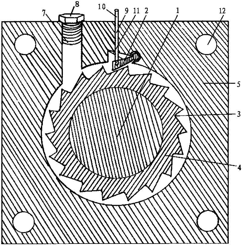
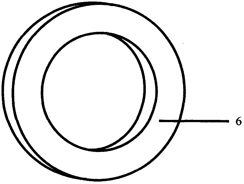
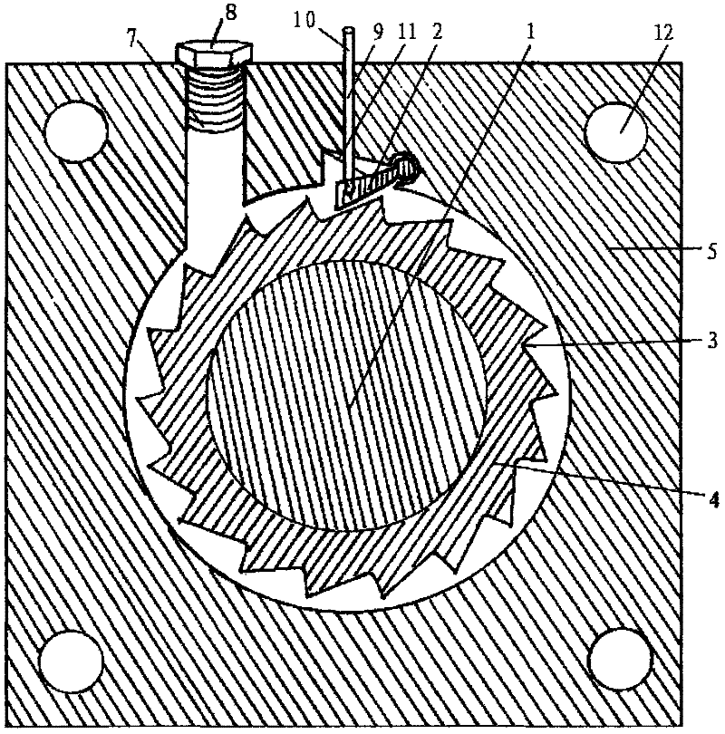
[0017] Anti-rollback structure of the present invention, such as figure 1 , 2 As shown, it includes the transmission output spindle of the automobile transmission 1, the anti-backward directional clip 2, the anti-backward directional card oblique concave-convex groove 3, the anti-backward directional card oblique concave-convex groove round seat 4, the fixed shell 5, the oil seal 6, and the oil injection hole 7 , Oil hole screw cover 8, control hole 9, control cable or pull rod 10, return spring 11, fixing hole 12.
[0018] The anti-backward directional card inclined concave-convex groove 3 is arranged on the periphery of the anti-backward directional card inclined concave-convex groove round seat 4, and the anti-backward directional card inclined concave-convex groove round seat 4 is pierced and fixed on the transmission output spindle 1 of the automobile transmission, and the outer shell is fixed. 5 is movable sleeved on the periphery of the round seat 4 of the inclined con...
PUM
Abstract
The invention discloses an automobile structure for preventing sliding back, which comprises a transmission output spindle of an automobile transmission, an orientating clip for preventing sliding back, an inclined concave-convex slot of the orientating clip for preventing sliding back, a circular base for the inclined concave-convex slot of the orientating clip for preventing sliding back, a returning spring, a fixed shell, an inhaul cable oil seal, a fixed hole, and the like, wherein the directions of the orientating clip for preventing sliding back and the inclined concave-convex slot of the orientating clip for preventing sliding back are only confined to a direction of forward motion of an automobile driven by an engine output and are blocked in reverse direction. The automobile structure provided by the invention has the following beneficial effects: when the automobile is stopped or started, if the automobile is in a forward gear, the automobile can only move forwards and cannot move back; when the automobile is uphill started, if the gear is suitable, the automobile is started as easy as on a level road and a downward slope; various traffic accidents caused by the sliding back under the influence of unsuitable operations of a driver are avoided, thereby realizing easily driving of the driver, saving oil and protecting environment, enhancing the safety of uphill starting, reducing abrasions of a braking friction part and a clutch, and meanwhile reducing waste gas pollution; and the automobile structure is simple in structure, is low in cost, is suitable for improving, mounting and preventing sliding back for various new and old automobiles and various new energy powered automobiles, and is beneficial to wide popularization and application.
Description
technical field [0001] The invention relates to an anti-rollback structure of an automobile. Background technique [0002] Existing various motor vehicles and new energy vehicles, as long as the electric locomotive starts on a slope, no matter how good the driver's technology is, there will be a phenomenon of slipping backwards, and if it is serious, it will collide with the vehicle behind it and cause traffic accidents. Accidents affect safety and traffic congestion, but until today, people have not found out its root cause and solved this long-standing problem. Now the car backsliding phenomenon is mainly due to the two-way operation from the transmission to the driving wheel, so as long as the clutch and brake are released when starting uphill, the vehicle will immediately backslip when the gear is not in gear and the refueling is not timely, which is very easy to cause an accident. Contents of the invention [0003] The object of the present invention is to provide an...
Claims
Application Information
Patent Timeline
Application Date:The date an application was filed.
Publication Date:The date a patent or application was officially published.
First Publication Date:The earliest publication date of a patent with the same application number.
Issue Date:Publication date of the patent grant document.
PCT Entry Date:The Entry date of PCT National Phase.
Estimated Expiry Date:The statutory expiry date of a patent right according to the Patent Law, and it is the longest term of protection that the patent right can achieve without the termination of the patent right due to other reasons(Term extension factor has been taken into account ).
Invalid Date:Actual expiry date is based on effective date or publication date of legal transaction data of invalid patent.