
Power switching device for vehicle

A power switching and vehicle technology, which is applied to control devices, vehicle components, transportation and packaging, etc., can solve problems such as insufficient displacement, insufficient displacement of the moving plate 14, and pulling clearance.

Inactive Publication Date: 2014-06-18
KYMCO
View PDF5 Cites 0 Cited by
  • Summary
  • Abstract
  • Description
  • Claims
  • Application Information

AI Technical Summary

Problems solved by technology

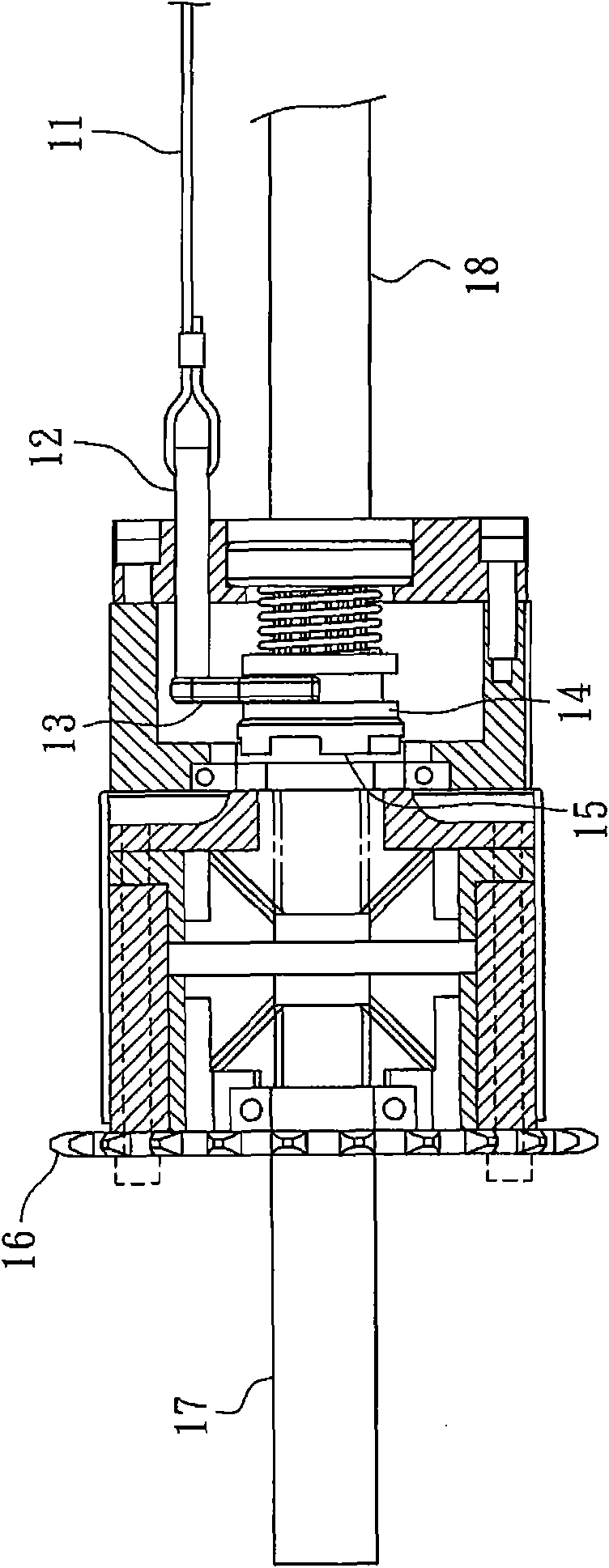
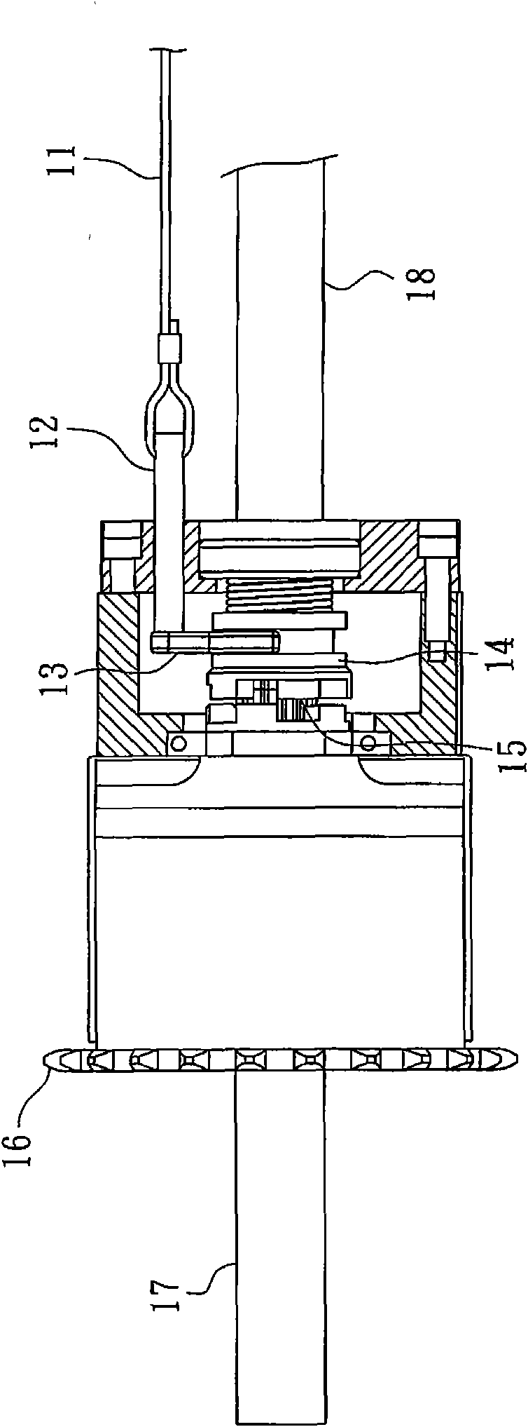
[0006] Although the steel wire rope 11 can be used to control the first and second drive shafts 17, 18 to rotate at a differential speed or be directly driven by the driving toothed disc 16, there is a problem of pulling clearance in the use of the steel wire rope 11, so , during use, the pulling clearance of the wire rope 11 must be overcome before the connecting shaft 12, the moving rake 13 and the moving plate 14 can be driven. Therefore, the displacement of the moving plate 14 is likely to be insufficient, thereby affecting the control of the second moving plate. 1. The stability of the second transmission shaft 17, 18; in order to avoid the problem of insufficient displacement of the moving plate 14 caused by the pulling clearance of the wire rope 11, it is necessary to install an additional detector to confirm the position of the moving plate 14

Method used


Image

  • Power switching device for vehicle
  • Power switching device for vehicle
  • Power switching device for vehicle

Examples


Embodiment Construction

[0056] The aforementioned and other technical contents, features and effects of the present invention will be clearly presented in the following detailed description of two preferred embodiments with reference to the drawings.

[0057] Before the present invention is described in detail, it should be noted that in the following description, similar elements are denoted by the same numerals.

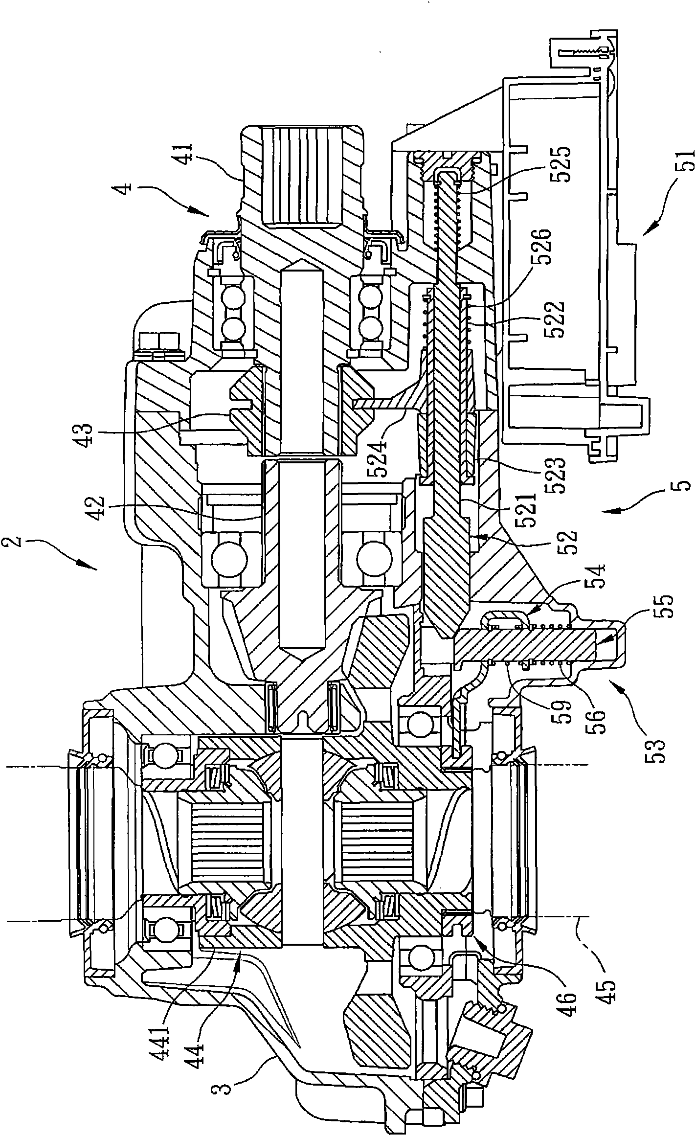
[0058] refer to image 3 , the power switching device 2 of the vehicle of the present invention includes a housing 3 , a power transmission unit 4 , and a drive unit 5 .

[0059] The power transmission unit 4 includes an input shaft 41 driven by the power of the vehicle (not shown in the figure) to rotate, an output shaft 42 spaced apart from the input shaft 41, an The second coupling member 43 that moves up, a differential 44 linked by the output shaft 42, a wheel shaft 45 connected to the differential 44, and a wheel shaft 45 that can be connected to the differential 44 The first coup...


PUM


Abstract

The invention discloses a power switching device for a vehicle. The power switching device comprises a power transferring unit and a drive unit. The power transferring unit comprises an input shaft, an output shaft which is separated from the input shaft, a second coupling piece which can move on the input shaft and the output shaft, and a first coupling piece which can move on an axle cylinder of a wheel axle and a differential. The drive unit comprises a control box, a first drive mechanism and a second drive mechanism. The control box can drive the first drive mechanism to drive the second drive mechanism to move, so that the first coupling piece is poked; therefore, the wheel axle does not generate differential power, or the first drive mechanism pokes the second coupling piece so as to switch drive power of the vehicle, the effects of high power switching stability and exact actuating are achieved, and a control mode can be simplified to ensure that the power switching device has the optimum integral design.

Description

【Technical field】 [0001] The present invention relates to a switching device, in particular to a vehicle power switching device. 【Background technique】 [0002] The distance between the left and right wheels of the vehicle will form a difference in the distance traveled when the vehicle turns, thus causing the risk of overturning. In order to solve this problem, a differential was developed to enable the left and right wheels of the vehicle to be different. It operates at a certain speed and provides good steering performance of the vehicle. [0003] However, when the vehicle is running on bad road conditions (for example: rough terrain, muddy ground, sandy ground, etc.), the friction and resistance of the left and right wheels must always be in an unbalanced state, resulting in a certain wheel being lost due to small friction. All the engine power causes idling, and the other wheel does not output any power, which will cause the vehicle to fail to move forward, or even sli...

Claims


Application Information

Patent Timeline
Patent Type & Authority Patents(China)
IPC IPC(8): B60K17/354B60K17/28B60K17/16
Inventor 张记函何昭昌
Owner KYMCO
Learn More