
An Optimal Algorithm for Fast Beam Adjustment of Large Angle Ion Implanter

An ion implanter and large-angle technology, which is applied in computing, special data processing applications, instruments, etc., to achieve the effects of rapid optimization of beam current, avoiding time consumption, and improving productivity

Active Publication Date: 2015-09-30
BEIJING SHUOKE ZHONGKEXIN ELECTRONICS EQUIP CO LTD
View PDF4 Cites 1 Cited by
  • Summary
  • Abstract
  • Description
  • Claims
  • Application Information

AI Technical Summary

Problems solved by technology

Beam Conditioning Has Been a Barrier to Improving Ion Implanter Productivity

Method used


Image

  • An Optimal Algorithm for Fast Beam Adjustment of Large Angle Ion Implanter
  • An Optimal Algorithm for Fast Beam Adjustment of Large Angle Ion Implanter

Examples


Embodiment Construction

[0015] Below in conjunction with accompanying drawing, the present invention will be further introduced.

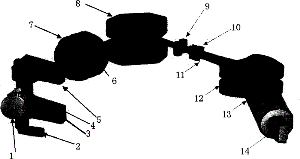
[0016] see figure 1 , the large-angle ion implanter includes: a long-life gas-solid dual-purpose ion source 1, a source magnetic field magnet 2, a three-dimensional (X / Y / Z) automatic adjustment system 3, an extraction suppression electrode 4, a pre-analysis magnetic field magnet 5. A focusing electrode 6, an accelerating tube 7, an analysis field magnet 8, a variable rotation analysis slot 9, a symmetrical double-electrode scanning plate 10, a fixed Faraday cup 11, a parallel lens magnet 12, and an ion beam 13 . A target chamber wafer processing system 14 .

[0017] The long-life gas-solid dual-purpose ion source 1 utilizes the substances entering the cavity to generate a large amount of plasma required. A large amount of plasma is extracted with a certain energy and enters the three-dimensional (X / Y / Z) automatic adjustment system 3. After the automatic position adjustm...


PUM


Abstract

The invention discloses an optimization algorithm for quickly adjusting a beam of a large-angle ion implantation machine. The beam current optimization algorithm uses a golden search algorithm and a scanning detection algorithm. The optimization algorithm has the largest characteristic that: when the large-angle ion implantation machine adjusts beam automatically, beam current can be adjusted within an extremely short time period and optimized beam adjustment can be performed; therefore, process data can be processed in real time and high-quality beam current can be acquired finally.

Description

technical field [0001] The invention relates to a large-angle ion implanter, in particular to an optimization algorithm for fast beam adjustment of the large-angle ion implanter, and belongs to the field of semiconductor device manufacturing. Background technique [0002] Ion implantation is a standard, commercially accepted technique for doping semiconductor wafers to alter their conductivity. There are limitations to the precision, implant depth, dose uniformity, and surface contamination damage of the implant manufacturing process. To form the desired substance on the semiconductor wafer, it needs to be implanted at different depths, and the particle beam energy required for different depths is also different. For different process formulations, different types of ions, different energies and different doses need to be implanted in several steps. The parameters of the ion beam are also changed over time periods. For example, when the energy of the ion beam is changed, ...

Claims


Application Information

Patent Timeline
Patent Type & Authority Patents(China)
IPC IPC(8): H01J37/317G06F17/50
Inventor 王迪平唐景庭伍三忠孙勇
Owner BEIJING SHUOKE ZHONGKEXIN ELECTRONICS EQUIP CO LTD
Learn More