
Pipeline type photoelectric water flow switch

A water flow switch and pipeline-type technology, which is applied in the field of water treatment control, can solve the problems of particles and sundries entering and damaging the transmission parts, the electromagnetic field environment requirements at the installation point are high, and the components are easily damaged, so as to avoid pollution and damage, and resist The effect of strong interference ability and fast response speed

Inactive Publication Date: 2017-02-15
YANGZHOU UNIV
View PDF6 Cites 0 Cited by
  • Summary
  • Abstract
  • Description
  • Claims
  • Application Information

AI Technical Summary

Problems solved by technology

The flow switches mentioned above all need to add sensing elements directly in contact with the liquid inside the pipeline. There are disadvantages such as the elements are easily damaged in the highly corrosive liquid, and the particles and sundries enter and damage the transmission parts. Some also have relatively high requirements for the electromagnetic field environment at the installation point. high

Method used


Image

  • Pipeline type photoelectric water flow switch
  • Pipeline type photoelectric water flow switch

Examples


Embodiment Construction

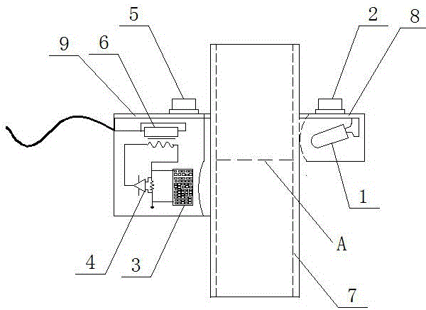
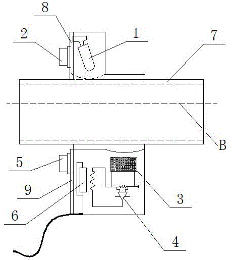
[0014] Such as figure 1 As shown, in the present invention, a line of infrared emitting diodes 1 and a beam emitting end angle adjuster 2 are arranged on one outer side of the transparent pipe 7 through a fixing frame 8. On the other outer side of the transparent pipe 1 a photocell 3 and a light beam receiving end are arranged through a fixing frame 9 The position adjuster 5, the detection circuit 6 and the amplifying circuit 4, and the signal output end of the photocell 3 is amplified by the amplifying circuit 4 and then connected to the detection circuit 6.

[0015] When the transparent pipe 7 is installed vertically, such as figure 1 As shown, the power cord is connected to the infrared emitting diode 1. The infrared emitting diode 1 emits an infrared beam. By adjusting the beam emitting end angle adjuster 2 and the beam receiving end position adjuster 5, when the liquid level does not reach the height of the control liquid level After the emitted light beam propagates through ...


PUM


Abstract

The invention provides a pipeline type photoelectric water flow switch, and relates to the technical field of water treatment control. An infrared emitting diode is arranged on one outer side of a transparent pipeline through a fixing support; and a photocell and a detection circuit are arranged on the other outer side of the transparent pipeline through a fixing support, wherein a signal output end of the photocell is connected to the detection circuit. According to the invention, the infrared emitting diode is adopted by an emitting end, the emitted infrared light beams are high in penetrability, are stable, and are long in wavelength, and light beams penetrating the pipeline are good in effect and are high in resistance to interference; and the photocell is adopted by an receiving end, the photocell is large in light receiving area, is high in sensitivity, is fast in response speed, is little in temperate influence, is high in resistance to interference, can effectively feed variation of water flow back, and can rapidly transmit a signal.

Description

Technical field [0001] The invention relates to the technical field of water treatment control, in particular to a water flow switch structure technology for liquid level control. Background technique [0002] Water flow switch is suitable for water circulation control, inlet and outlet water control, water heating control, water pump switch control, solenoid valve on-off control, or water outlet power off, water outlet power control, etc. in the field of water treatment control. It is a kind of water flow after the water flow reaches a certain flow. A sensor device that converts into a switch-type electrical signal. According to different principles, water flow switches mainly include: gravity type water flow switch, which requires high water quality, and must be installed upright; piston type water flow switch requires a magnetic ring in the piston and pushes the piston by water pressure, and the cost is slightly higher; The rotor-type water flow switch cannot rotate or is inf...

Claims


Application Information

Patent Timeline
IPC IPC(8): G01F23/292
CPCG01F23/292
Inventor 张键仇鑫曹爱辉孙传芝林舒康
Owner YANGZHOU UNIV
Learn More