Display panel of transflective transparent display and sub-pixel structure thereof

A semi-transmissive, semi-reflective and transparent display technology, applied in instruments, nonlinear optics, optics, etc., can solve the problems of the panel not having transparent characteristics and increasing the cost.

Active Publication Date: 2011-11-23
NANJING CEC PANDA LCD TECH
View PDF3 Cites 11 Cited by
  • Summary
  • Abstract
  • Description
  • Claims
  • Application Information

AI Technical Summary

Problems solved by technology

At present, LCDs with semi-transmissive and semi-reflective technology have polarizers, 1/4 wave plates, and sub-pixel electrodes on the first substrate in the transmissive area, and ITO

Method used


Image

  • Display panel of transflective transparent display and sub-pixel structure thereof
  • Display panel of transflective transparent display and sub-pixel structure thereof
  • Display panel of transflective transparent display and sub-pixel structure thereof

Examples


Example Embodiment

[0026] Example 1-A:

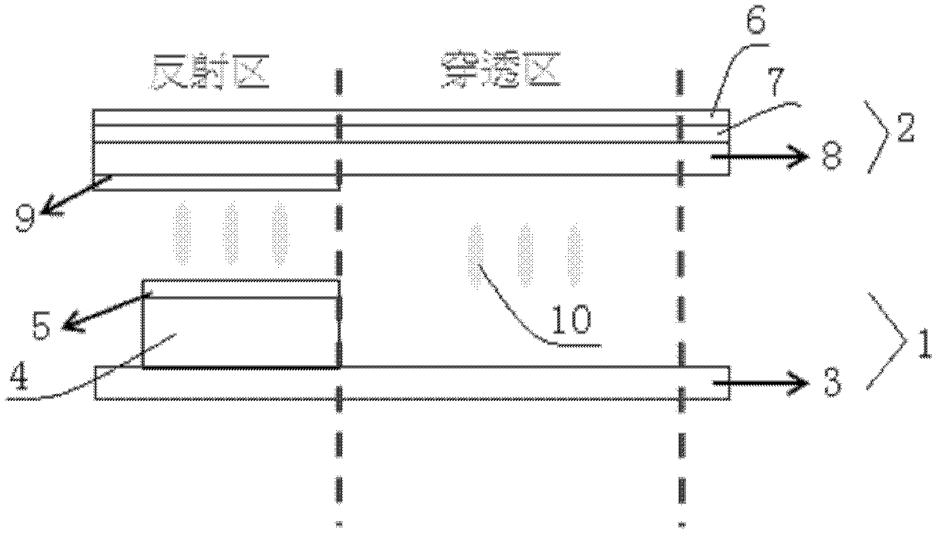
[0027] Such as figure 1 As shown, the pixel structure of the present embodiment includes a first substrate 1 and a second substrate 2 oppositely arranged. The left area of ​​the two substrates is the reflection area of ​​the sub-pixel, the right area is the penetration area of ​​the sub-pixel, and the first substrate 1 includes a first glass 3, a reflective layer 4 provided on the reflective area of ​​the first glass 3, and a sub-pixel electrode 5 provided on the reflective layer 4. The second substrate 2 includes a polarizing plate 6 arranged in sequence, a quarter wave Sheet 7, second glass 8, and ITO layer 9 on the reflective area of ​​second glass 8, without color filters; multiple sub-pixel structures and a liquid crystal layer arranged between the first substrate 1 and the second substrate 2 10 constitutes a display panel. Compared with the prior art, the first substrate has no backlight, polarizer and quarter-wave plate, and the second glass does no...

Example Embodiment

[0028] Example 1-B:

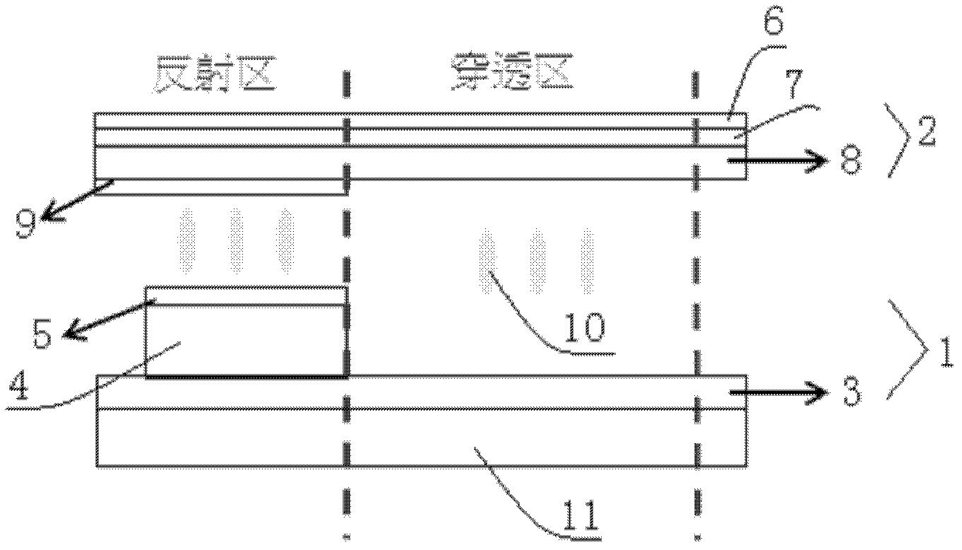
[0029] Such as figure 2 As shown, the difference between this embodiment and embodiment 1-A is that the outer side of the first glass 3 is also provided with an LED backlight source 11, and the LED backlight source is used to strengthen the light source under the dark room, so that the panel can display content more clearly. Suitable for darkroom environment.

Example Embodiment

[0030] Example 2-A:

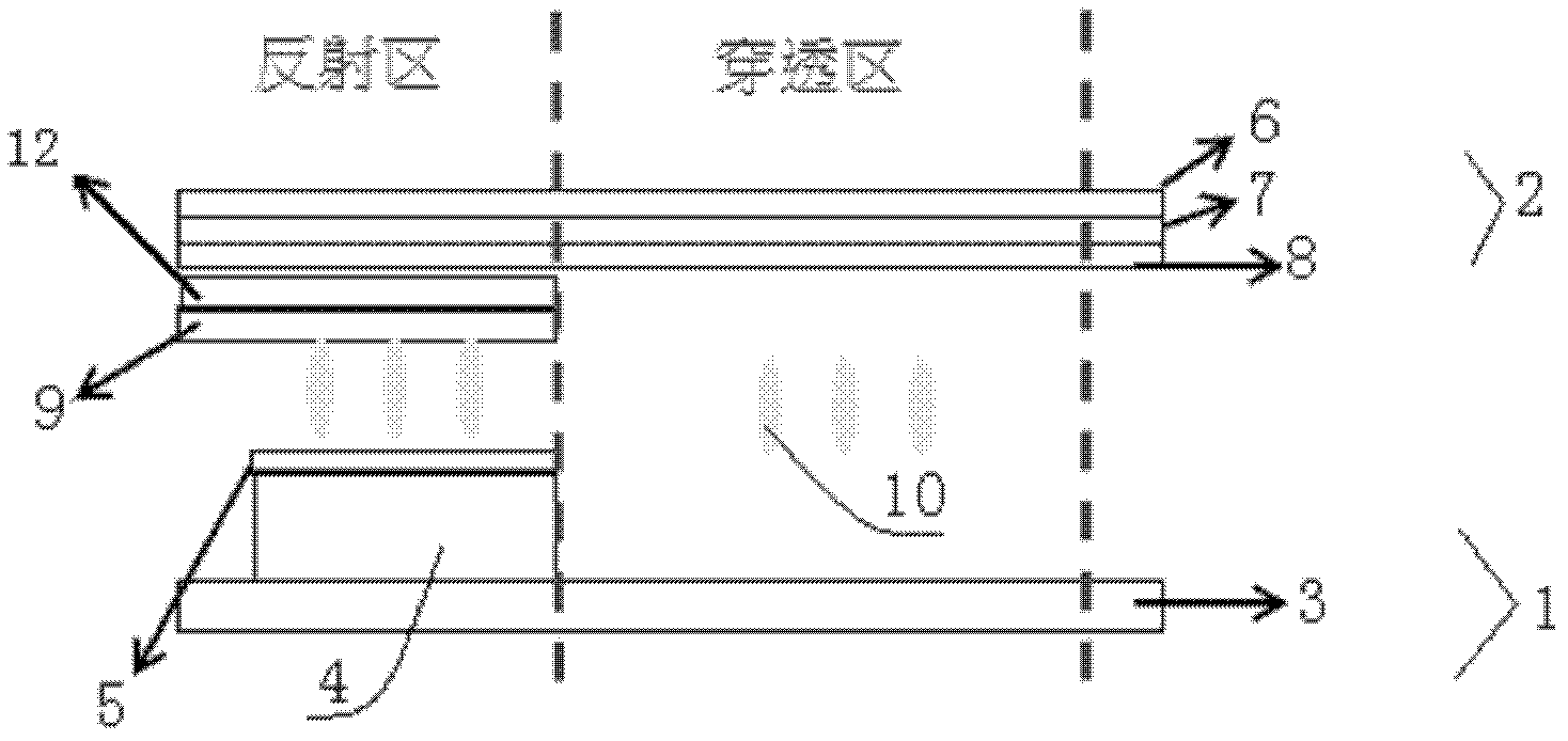
[0031] Such as image 3 As shown, the difference between this embodiment and embodiment 1-A is that the second glass 8 is located between the reflective area and the ITO layer 9 and is also provided with a color filter 12 to realize color image display, and the design in the penetrating area There is no color filter to increase the transparency of the panel.


PUM


Abstract

The invention discloses a sub-pixel structure of a transflective transparent display. The sub-pixel structure comprises a first substrate and a second substrate which are arranged oppositely, wherein the areas corresponding to the first substrate and the second substrate are respectively divided into a reflecting area and a transmitting area; the first substrate comprises first glass, wherein the part of the first glass, which is positioned in the reflecting area, is provided with a reflecting layer at one side relative to the second substrate, and a sub-pixel electrode is arranged on the reflecting layer; and the second substrate comprises a polarizer, wherein the polarizer is provided with a quarter wave plate at the side relative to the first substrate, the quarter wave plate is provided with a second glass, and the part of the second glass, which is positioned in the reflecting area, is provided with an ITO (Indium Tin Oxide) layer. The invention also discloses a display panel comprising the sub-pixel structure. The display area of the display panel disclosed by the invention has a transparent characteristic; and in a condition that a backlight source is arranged, the display panel can also be used in a darkroom environment.

Description

Technical field [0001] The invention relates to a display device, in particular to a display panel of a semi-transmissive and semi-reflective transparent display and its sub-pixel structure. Background technique [0002] Liquid crystal displays are non-self-luminous displays and require an external light source to provide sufficient brightness for the liquid crystal panel. Generally used liquid crystal display products such as laptop or desktop computer screens are transmissive LCDs. Transmissive LCD needs to rely on a backlight module as a light source, and most of the power is consumed by the backlight device. However, since portable products such as mobile phones, PDAs, and digital cameras have strict requirements on power saving, transmissive LCDs with backlights are less suitable for portable products. In addition, portable products need to be used outdoors often When the outdoor sunlight is too large, the transmissive LCD will appear dim and have low contrast between light...

Claims


Application Information

Patent Timeline
IPC IPC(8): G02F1/1335G02F1/13357G02F1/1362G02F1/1343
Inventor 林佳玲何建国
Owner NANJING CEC PANDA LCD TECH
Why Eureka
Try Eureka