
A vacuum electron beam welding fixture for aluminum alloy structural parts with ic equipment

A technology of vacuum electron beam and welding fixture, which is applied in the direction of electron beam welding equipment, welding equipment, welding equipment, etc., to achieve the effects of stable and reliable direction, reliable clamping and positioning, and simple structure

Inactive Publication Date: 2015-09-09
SHENYANG INST OF AUTOMATION - CHINESE ACAD OF SCI
View PDF7 Cites 0 Cited by
  • Summary
  • Abstract
  • Description
  • Claims
  • Application Information

AI Technical Summary

Problems solved by technology

The welding fixture can effectively clamp the IC equipment aluminum alloy structural parts for welding on the existing vacuum electron beam welding machine

Method used


Image

  • A vacuum electron beam welding fixture for aluminum alloy structural parts with ic equipment

Examples


Embodiment Construction

[0017] The present invention will be described in further detail below in conjunction with the accompanying drawings.

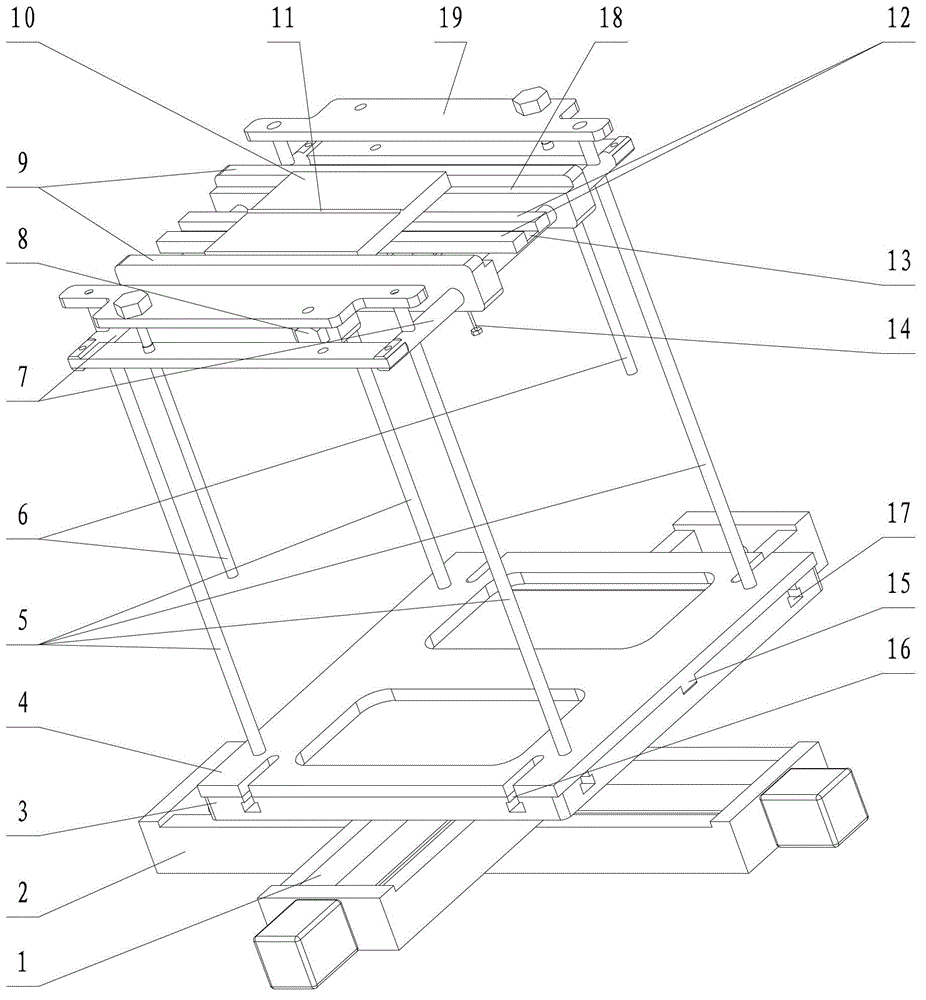
[0018] Such as figure 1 As shown, the present invention includes a two-dimensional numerical control platform, a beam frame 7, a clamping slider 9, a backing plate 12 and a horizontal plate 19, wherein the two-dimensional numerical control platform is installed on a vacuum electron beam welding machine, and includes an X-axis slide table 1, Y-axis sliding table 2 and worktable 3, X-axis sliding table 1 is installed on the screw nut of Y-axis sliding table 2, and is threadedly connected with the screw of Y-axis sliding table 2 through the screw nut, along the screw of Y-axis sliding table 2 Reciprocating movement; worktable 3 is installed on the screw nut of X-axis slide 1, and is threadedly connected with the screw of X-axis slide 1 through the screw nut, reciprocatingly moves along the screw of X-axis slide 1, and moves with the X-axis slide 1 The lead scre...


PUM


Abstract

The invention belongs to the field of aluminum alloy structure members of IC (integrate circuit) equipment, and particularly relates to a vacuum electron beam welding jig for aluminum alloy structure members of IC equipment. The vacuum electron beam welding jig comprises a two-dimensional numerical control platform, a beam frame, clamping sliders, base plates and cross plates. The cross plates are disposed on the two-dimensional numerical control platform through uprights, and adjusting screws for adjusting working distance are arranged on the cross plates; the beam frame sleeving the uprights is in threaded connection with the adjusting screws and performs axial reciprocating movement along the uprights through rotation of the adjusting screws; the beam frame is sleeved with the clamping sliders which are clamped in the middle of a welded work piece, one side of the work piece is supported through the clamping sliders, the other side of the work piece is supported through the base plates laid on the beam frame, and clamping screws used for adjusting the clamping distance are arranged on the clamping sliders. The vacuum electron beam welding jig has the advantages of simple structure, light mass, convenience in use, low cost and the like, production efficiency can be improved, and evenness and stability of welding quality are guaranteed.

Description

technical field [0001] The invention belongs to the field of welding aluminum alloy structural parts of IC equipment, in particular to a vacuum electron beam welding jig for aluminum alloy structural parts of IC equipment. Background technique [0002] Different from the single functional requirements of components in other industries, the components of IC (integrate circuit, integrated circuit) equipment often have to take into account the complex functional requirements such as strength, strain, corrosion resistance, electronic characteristics, electromagnetic characteristics, and material purity. The complex integration of technology often uses aluminum alloy materials. The structural parts of IC equipment generally require extremely high machining accuracy. In order to meet the requirements of high-precision welding of IC equipment and solve the problem of difficult welding of aluminum alloys, the welding rods are used, which are not easy to oxidize, good process repeata...

Claims


Application Information

Patent Timeline
Patent Type & Authority Patents(China)
IPC IPC(8): B23K15/06B23K37/04B23K37/00
CPCB23K15/0013B23K15/0053B23K15/06
Inventor 乔红超赵吉宾于彦凤
Owner SHENYANG INST OF AUTOMATION - CHINESE ACAD OF SCI
Learn More