
Multiple conductor winding in stator

A stator and coil technology, applied in the shape/style/structure of winding conductors, the shape/style/structure of winding insulation, electric components, etc., can solve the problems of increasing the effective resistance and resistance loss of conductors

Active Publication Date: 2012-02-08
HAMILTON SUNDSTRAND CORP
View PDF5 Cites 8 Cited by
  • Summary
  • Abstract
  • Description
  • Claims
  • Application Information

AI Technical Summary

Problems solved by technology

As a result, eddy currents in the conductor increase the effective resistance and resistive losses of the conductor

Method used


Image

  • Multiple conductor winding in stator
  • Multiple conductor winding in stator
  • Multiple conductor winding in stator

Examples


Embodiment Construction

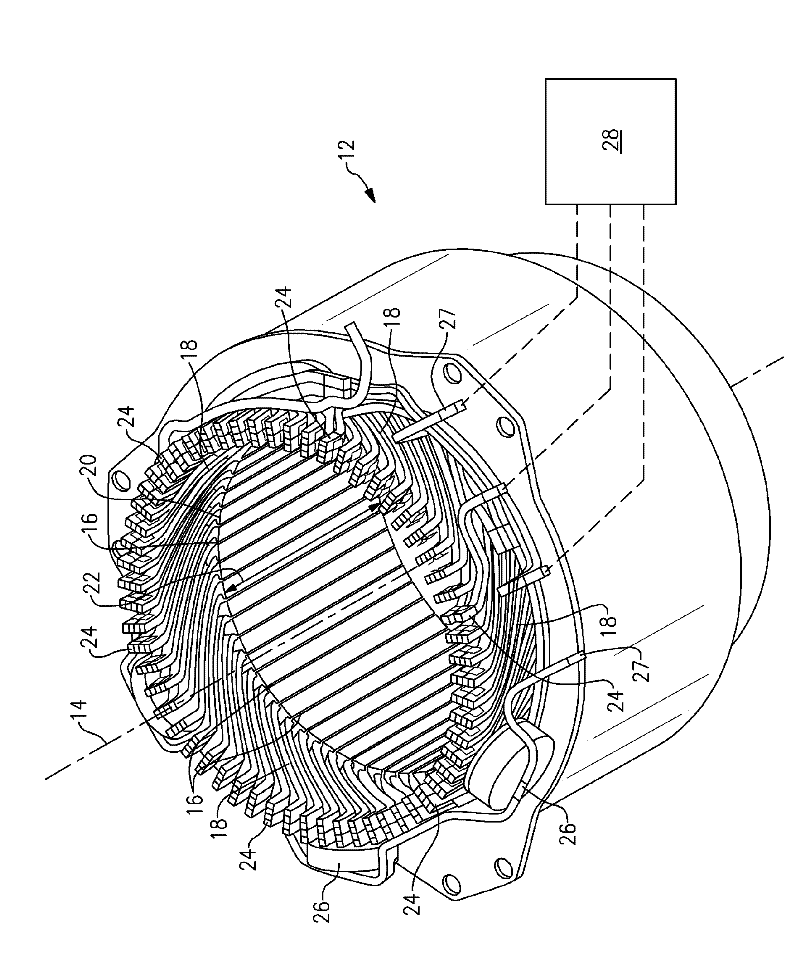
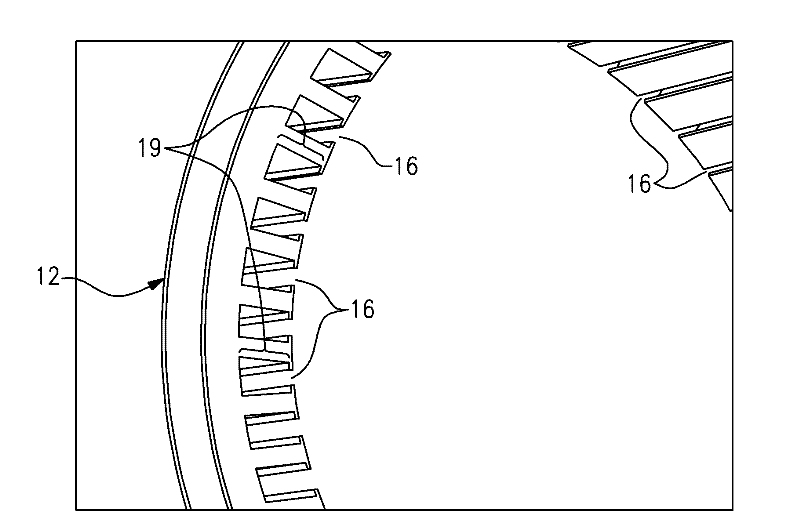
[0020] see figure 1 , schematically shows an exemplary electric machine 10 such as a generator or auxiliary power unit. As shown, the electric machine 10 includes a stator 12 in register with a rotor 13 . However, it is within the contemplation of the present disclosure to use any wound stator 12 and rotor 13 arrangement, as well as to use electric machine 10 with more components or a different arrangement. The electric machine is driven by a prime mover 15, such as a gas turbine engine for aerospace applications. As shown, shaft 17 couples prime mover 15 and rotor 13 . However, it is within the contemplation of the present disclosure to use other prime movers and coupling arrangements. In one embodiment, the housing assembly 11 includes an input housing 23 that encloses various components of the electric machine 10 . However, housing assemblies including more components and different arrangements are also within the contemplation of the present disclosure. In one example...


PUM


Abstract

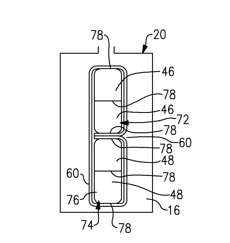
An electric machine includes a stator disposed about an axis in register with the rotor. The stator has a plurality of slots parallel to the axis. A plurality of windings with generally rectangular cross sections is provided with each winding having a first portion disposed radially inward of a second portion relative to the axis. At least two of the plurality of windings are at least partially inserted into each of the plurality of slots. The plurality of generally rectangular windings in each of the plurality of slots is configured to reduce resistive loss within the stator.

Description

technical field [0001] The present disclosure relates generally to electric machines, including generators and electric motors having stators with electrical coils. Background technique [0002] Electric machines, such as generators, are commonly used to convert mechanical energy into electrical energy. An electric machine typically includes a stator and a rotor in register therewith. The stator includes electrical coils that allow alternating current ("AC") current to flow through the stator. Movement of the rotor relative to the stator causes AC current to move through the coils. Electrical connections such as power buses are provided between the coils and the various components to allow current to flow between the stator and the various components acting as loads. [0003] As a result of the AC current in the coil, the coil experiences eddy current losses. Eddy current losses are caused by the cross slot flux induced by the AC current in the coil. The cross-slot flux...

Claims


Application Information

Patent Timeline
IPC IPC(8): H02K3/04H02K3/12H02K3/28
CPCH02K3/12H02K3/34H02K3/505H02K15/064Y10T29/49009H02K3/28H02K15/062
Inventor D.帕特尔D.R.霍赫斯特勒G.W.弗里斯克
Owner HAMILTON SUNDSTRAND CORP
Learn More