Self-adapting interference cancellation device and debugging method thereof

An interference cancellation and self-adaptive technology, applied to electrical components, transmission systems, etc., can solve problems such as receiver blocking

Active Publication Date: 2012-02-08
CHINA SHIP DEV & DESIGN CENT
View PDF2 Cites 44 Cited by
  • Summary
  • Abstract
  • Description
  • Claims
  • Application Information

AI Technical Summary

Problems solved by technology

When the transmitting antenna transmits with high power, it will couple a lar

Method used


Image

  • Self-adapting interference cancellation device and debugging method thereof
  • Self-adapting interference cancellation device and debugging method thereof
  • Self-adapting interference cancellation device and debugging method thereof

Examples


Embodiment Construction

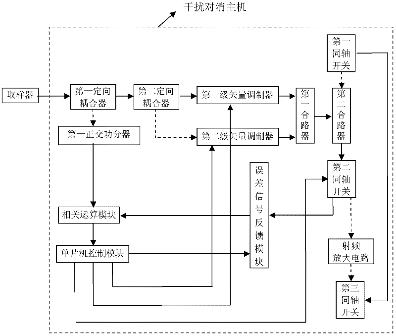
[0062] Further illustrate the present invention below in conjunction with accompanying drawing, an embodiment of the present invention is for example figure 1 As shown, the hardware structure can be divided into two parts: the sampler and the cancellation host, where the cancellation host includes a control module, a correlation calculation module, a first directional coupler, a first quadrature power divider, and a second directional coupler , the first stage vector modulator, the second stage vector modulator, the first combiner, the second combiner, the first coaxial switch, the second coaxial switch, the first radio frequency amplifier circuit, the third coaxial switch and error signal feedback module.

[0063] The sampler is connected to the input end of the first directional coupler, the output end of the first directional coupler is connected to the input end of the second directional coupler, and the coupling end of the first directional coupler is connected to the fir...


PUM


Abstract

The invention provides a self-adapting interference cancellation device adopting a technical scheme of two-stage cancellation, namely the interference margin of the first-stage cancellation is used as the interference input of the second-stage cancellation to perform interference cancellation twice, which is the theory of two-stage interference cancellation. Therefore, the residual interference signal components can be further reduced. Two-stage interference cancellation is performed in sequence, namely the second-stage interference cancellation process is performed after the first-stage interference cancellation process is finished, and the second-stage programmable attenuator is in a full attenuation state in the first-stage interference cancellation process. The self-adapting interference cancellation device is mainly applied to elimination of coupling interference among co-location dual-mode antennae, and inhibits the coupling interference among co-site dual-mode antennae without reducing the spectrum resource utilization rate.

Description

technical field [0001] The invention belongs to an electromagnetic interference control device, in particular to an adaptive interference cancellation device, which is used for suppressing coupling interference between transmitting and receiving antennas in a common site. Background technique [0002] Coupling interference between transmitting and receiving antennas in a common site is one of the common forms of electromagnetic interference. Since the transmitting and receiving antennas are arranged on the same site, the distance between them is small and the isolation is low. The transmitting power of the transmitting antenna is usually high, reaching hundreds of watts or even kilowatts, which will generate a large coupling voltage (from tens of mV to several V) at the nearby receiving antenna, which will form strong interference The power will seriously affect the normal operation of the receiver, causing the receiver to be blocked or even burned. For example, on a ship,...

Claims


Application Information

Patent Timeline
IPC IPC(8): H04B1/10
Inventor 谭辉宋文武王玉珏刘义张崎
Owner CHINA SHIP DEV & DESIGN CENT
Why Eureka
Try Eureka