Power driving circuit

A power drive circuit and loop technology, applied in the field of aviation electrical, can solve the problems of complex related circuits, grid voltage fluctuations, power waveform distortion, etc., and achieve the effects of no waveform distortion, small electromagnetic interference, and simple and reliable trigger circuit

Inactive Publication Date: 2016-02-24
天津航空机电有限公司
View PDF3 Cites 0 Cited by
  • Summary
  • Abstract
  • Description
  • Claims
  • Application Information

AI Technical Summary

Problems solved by technology

[0003] The commonly used thyristor trigger circuit is connected to the main circuit due to the connection of high-power electricity, which is easily affected by the fluctuation of the grid voltage and the distortion of the power waveform. At the same time, in order to solve the synchronization problem, the related circuits are also relatively complicated.

Method used


Image

  • Power driving circuit
  • Power driving circuit
  • Power driving circuit

Examples


Embodiment 1

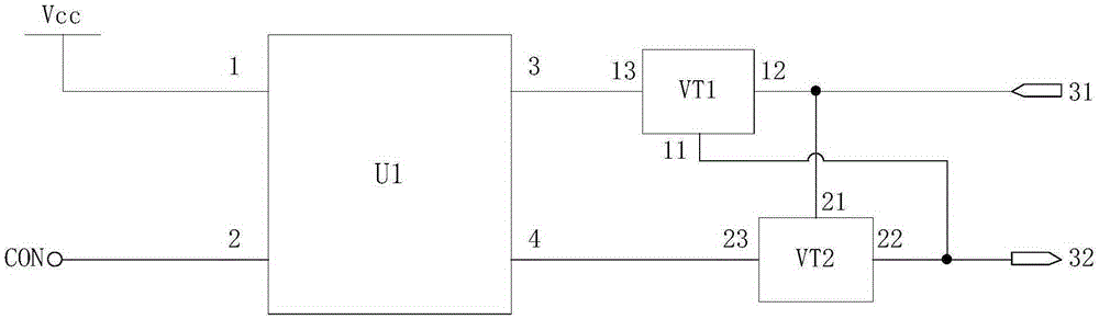
[0031] figure 1 It is a schematic structural diagram of a power drive circuit provided by Embodiment 1 of the present invention. This embodiment is applicable to a power drive circuit of a propeller sequential heating controller. The power drive circuit includes:

[0032] Photocoupler U1, the first thyristor loop VT1 and the second thyristor loop VT2; where

[0033] The first input pin 1 of the photocoupler U1 is connected to the constant voltage power supply Vcc, and the second input pin 2 of the photocoupler U1 is connected to the control signal for generating two driving signals according to the control signal CON. The first output pin 3 and the second output pin 4 output;

[0034] The first output pin 3 of the photocoupler U1 is connected to the gate 13 of the first thyristor circuit VT1, and the second output pin 4 of the photocoupler U1 is connected to the gate 23 of the second thyristor circuit VT2;

[0035] The anode 12 of the first thyristor circuit VT1 and the cath...

Embodiment 2

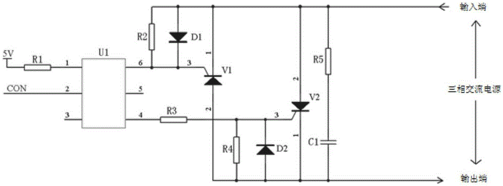
[0042] image 3 A circuit diagram of a power drive circuit provided by Embodiment 2 of the present invention. The technical solution provided by this embodiment is based on the above embodiments, and further includes: a series absorbing capacitor and a absorbing resistor, forming a resistance-capacitance absorbing circuit, and connecting in parallel at both ends of the thyristor loop.

[0043] Such as image 3 As shown, the snubber capacitor C1 and the snubber resistor R5 are connected in series and connected in parallel between the anode and cathode of the thyristor V2.


PUM


Abstract

The invention discloses a power driving circuit. The circuit comprises: a photocoupler, a first thyristor loop, and a second thyristor loop, a first input pin of the photocoupler is connected with a constant voltage power supply, a second input pin of the photocoupler is connected with a control signal and used for generating two channels of driving signals according to the control signal and outputting the driving signals from a first output pin and a second output pin of the photocoupler, the first output pin of the photocoupler is connected with a gate electrode of the first thyristor loop, the second output pin of the photocoupler is connected with a gate electrode of the second thyristor loop, an anode of the first thyristor loop and a cathode of the second thyristor loop are connected with an input terminal of a three-phase alternating current power supply, and a cathode of the first thyristor loop and an anode of the second thyristor loop are connected with an output terminal of the three-phase alternating current power supply. According to the power driving circuit, the photocoupler is employed to trigger thyristors, and the trigger circuit is simple and reliable.

Description

technical field [0001] Embodiments of the present invention relate to aviation electrical technology, and in particular to a power drive circuit. Background technique [0002] The thyristor has the characteristics of a silicon rectifier device, can work under high voltage and high current conditions, and its working process can be controlled, and the trigger circuit is simple, so it is widely used as an AC non-contact switch to drive AC high-power loads, and the thyristor is suitable for use in In the power drive circuit of the propeller sequential heating controller. [0003] The commonly used thyristor trigger circuit and the main circuit are connected with high-power electricity, which is easily affected by grid voltage fluctuations and power waveform distortion. At the same time, in order to solve the synchronization problem, the related circuits are also relatively complicated. Contents of the invention [0004] The invention provides a power driving circuit to reali...

Claims


Application Information

Patent Timeline
Patent Type & Authority Applications(China)
IPC IPC(8): H03K17/79
CPCH03K17/79
Inventor 刘强秦余贞刘义国仝步升
Owner 天津航空机电有限公司
Why Eureka
Try Eureka