
Composite wave separation method for moveout correction

A separation method and time difference correction technology, applied in seismology, instruments, measuring devices, etc., can solve the problems of waveform elongation, failure to eliminate waveform distortion, low frequency and other problems, and achieve the effect of meeting the needs of event alignment

Active Publication Date: 2018-12-28
CHINA PETROLEUM & CHEM CORP +1
View PDF5 Cites 0 Cited by
  • Summary
  • Abstract
  • Description
  • Claims
  • Application Information

AI Technical Summary

Problems solved by technology

[0010] The method of dynamic correction or eliminating the residual time difference of dynamic correction can make the event axis level, but still can not eliminate the waveform distortion
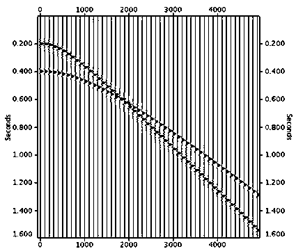
This kind of waveform distortion caused by time difference correction usually occurs in shallow layers and large offsets. The specific performance is that the waveform is elongated, the frequency is lowered, and when the events interfere with each other, the waveforms are mixed together, and the correction quality is more difficult to guarantee.
In conventional seismic data processing, the data stretched beyond a certain ratio is usually cut off, so that the seismic data at the shallow and far-offset distances are mostly cut off due to severe stretching, resulting in a reduction in the number of coverages and cannot be well utilized

Method used

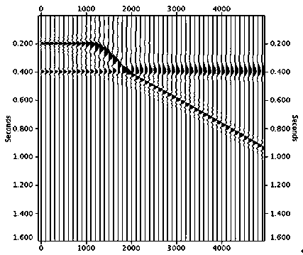
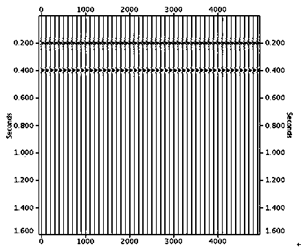

Image

  • Composite wave separation method for moveout correction
  • Composite wave separation method for moveout correction
  • Composite wave separation method for moveout correction

Examples


Embodiment 1

[0046] Example 1. A composite wave separation method for time difference correction, comprising the steps of:

[0047] Step 1: Analyze the input seismic data, and select the seismic traces with no aliasing in each waveform as the standard traces.

[0048] Step 2: Compare and analyze the waveform difference between the channel to be separated and the standard channel, divide the time window from the shallow layer to the deep layer, and determine the length of the time window according to the unaliased waveform part in the wave group of the channel to be separated.

[0049] Step 3: Slide the time window and calculate the correlation coefficient between the to-be-separated track and the standard track in a single time window, so that the waveforms of the to-be-separated track and the standard track can basically match.

[0050] Step 4: Calculate the amplitude ratio of the track to be separated and the standard track, and subtract the product of the standard track and the amplitu...

Embodiment 2

[0055] Example 2. A composite wave separation method for time difference correction, the method includes:

[0056] Step 1, select the standard trace, and use the multi-channel data with near-offset waveforms without aliasing to generate the standard trace through conventional dynamic correction and superposition;

[0057] Step 2, select the data time window, compare and analyze the waveform difference between the channel to be separated and the standard channel, and select the time window reasonably according to the non-aliasing part of the wave group to be separated;

[0058] Step 3, sliding the time window so that the cross-correlation coefficient reaches the threshold standard, the waveforms of the track to be separated and the standard track are basically consistent, and the amplitude ratio between the track to be separated and the standard track is calculated;

[0059] Step 4, subtracting the product of the standard track and the amplitude ratio from the track to be sepa...

Embodiment 3

[0063] Example 3. A composite wave separation method for time difference correction. The composite wave separation method includes:

[0064] Step 1, analyze the seismic data, and select the standard trace reasonably;

[0065] Step 2, select the data time window, compare and analyze the waveform difference between the channel to be separated and the standard channel, and select the time window reasonably according to the non-aliasing part of the wave group to be separated;

[0066] Step 3, calculate the cross-correlation coefficient between the track to be separated and the standard track, and slide the time window at the same time, so that the waveforms of the two are basically consistent, and calculate the amplitude ratio between the track to be separated and the standard track;

[0067] Step 4, subtracting the product of the standard track and the amplitude ratio from the track to be separated, thereby stripping the influence of the waveform data in a certain time window; ...


PUM


Abstract

The invention discloses a moveout correction-oriented superposed wave separating method. The moveout correction-oriented superposed wave separating method comprises steps that seismic data is analyzed, and a standard channel is selected reasonably; a cross correlation coefficient of a to-be-separated channel and the standard channel is calculated, and at the same time, a time window slides, and the waveform of the to-be-separated channel and the waveform of the standard channel are basically identical to each other, and the amplitude ratio of the to-be-separated channel and the standard channel is calculated; the product of the standard and the amplitude ratio is subtracted from the to-be-separated channel, and therefore influences of waveform data in a first time window are stripped; by adopting the same idea, other seismic waves are stripped iteratively, and then the superposed wave separation is realized, and the separated waves are combined together according to the corresponding moveout; and finally the seismic data after the waveform separation is output. Defects of conventional moveout correction methods are overcome, and the superposed wave separation is realized, and therefore dynamic correction tension effect is eliminated, and event flattening quality is high.

Description

technical field [0001] The invention relates to the field of seismic data processing, in particular to a composite wave separation method capable of realizing seismic wave time difference correction. Background technique [0002] The time difference correction of seismic data, also known as motion correction, is one of the basic contents of seismic data processing. Its function is to eliminate the influence of offset on the propagation time of reflected seismic waves and to alias together far offsets. Waveforms are separated to level the reflected wave events in the CMP gather. Whether the aliasing waves can be separated correctly will directly affect the quality of subsequent processing such as migration imaging. Conventional correction methods have problems such as unbalanced events and large offset stretching distortion, and the effect is particularly poor for seismic traces where waveforms are aliased and interfered together. [0003] The time-distance equation of the ...

Claims


Application Information

Patent Timeline
Patent Type & Authority Patents(China)
IPC IPC(8): G01V1/36
CPCG01V1/362G01V2210/52
Inventor 王延光刘立彬汪浩孙成禹张达慎国强王玉梅揭景荣李美梅王荣伟王振涛王希萍钮学民李海涛李燕张洪张睿璇
Owner CHINA PETROLEUM & CHEM CORP
Learn More