Inspection device for defect inspection

A detection equipment, defect detection technology, applied in the direction of measuring device, measuring perimeter, using optical devices, etc., can solve the problems of steep brightness gradient, not providing brightness gradient, unable to obtain accurate images, etc.

Inactive Publication Date: 2012-02-08
3B SYST INC
View PDF3 Cites 10 Cited by
  • Summary
  • Abstract
  • Description
  • Claims
  • Application Information

AI Technical Summary

Problems solved by technology

[0011] In this way, when the luminance rapidly changes to 0 luminance units on dark areas and 2 luminance units due to defect 11 on bright areas, an accurate image of defect 11 cannot be obtained because the bright areas are closely aligned with the dark areas. There's this very steep brightness gradient between regions
That is, such a rapid brightness change does not provide a brightness gradient, and only forms the outline of the defect 11 on the screen 9, thereby making it difficult to recognize the actual shape of the defect 11

Method used


Image

  • Inspection device for defect inspection
  • Inspection device for defect inspection
  • Inspection device for defect inspection

Examples


Embodiment Construction

[0034] Hereinafter, exemplary embodiments of the present invention will be described in detail with reference to the accompanying drawings.

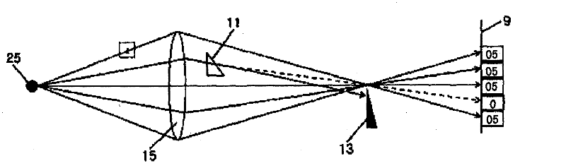
[0035] image 3 is an optical diagram explaining the principle of the knife edge in the detection device according to the present invention.

[0036] A point light source 25 is located at the left focus of the field lens 15 , and light emitted from the light source 25 is irradiated onto the screen 9 through the right focus of the field lens 15 . When there is a defect 11 between the field lens 15 and the right focal point of the field lens 15, the optical path of the light passing through the defect 11 is refracted and deviates from the normal optical path shown by the dotted line, thereby terminating at rather than passing through Through the knife edge (ie the knife edge 13, which may have a sharp plate-shaped end) located at this right focus.

[0037] Also, assuming from image 3 The intensity of the light emitted by the shown ligh...


PUM


Abstract

The present invention comprises an inspection method for transparent or reflective inspection objects, by using a retroreflective plate as a convex lens or concave mirror in such a way that defects can be detected in a stable fashion even if the inspection object is curved or if vibration occurs during movement of the inspection object; in which displacement of parallel light passing through or reflected in a measurement field is captured by using changes which occur in an inspection field, namely changes in the density gradient in the case of transmission inspection or in the reflection angle in the case of reflection inspection.; The present invention also comprises an inspection device for defect inspection, in which a knife edge is provided, horizontally to the optical axis, on the front surface of a camera lens for collecting the transmitted light or reflected light, in such a way that three-dimensional defect images can be obtained since any light which diverges from the parallel light is blocked with consequent changes in the contrast of the light due to the density gradient in the inspection field at the camera.

Description

technical field [0001] The present invention relates to inspection equipment for inspecting defects such as air bubbles, minute deformations, foreign matter, voids, etc. formed in or on an inspection object such as an opaque or transparent thin plate. More particularly, the present invention relates to an inspection apparatus including a knife edge and a retroreflective plate to stably provide clear images of defects even when an inspection object is subjected to vibration or has curved portions. Background technique [0002] figure 1 A planar light beam is shown incident on an upwardly or downwardly curved reflective plate in a general reflector optical system. [0003] figure 1 The left side of shows the optical path formed by the detection object bent upwards at one end, and figure 1 The right side of the shows the optical path formed by the detection object bent down at one end. [0004] Such as figure 1 As shown on the left side of , when a planar light beam is emi...

Claims


Application Information

Patent Timeline
Patent Type & Authority Applications(China)
IPC IPC(8): G01B11/16G02B13/00G02B5/00
CPCG01N21/8901G02B5/12G02B27/50G01B5/025G01B11/024
Inventor 李济善张玑秀
Owner 3B SYST INC
Why Eureka
Try Eureka